
Abstract: This article focuses on the research of spiral bevel gear active wheel near-net rolling forming technology. It includes the construction of mathematical models, numerical simulations, defect analyses, and quality control strategies. Through experimental research and verification, the feasibility and effectiveness of the proposed methods are demonstrated, aiming to improve the manufacturing quality and performance of spiral bevel gears.
1. Introduction
1.1 Spiral Bevel Gear Basics
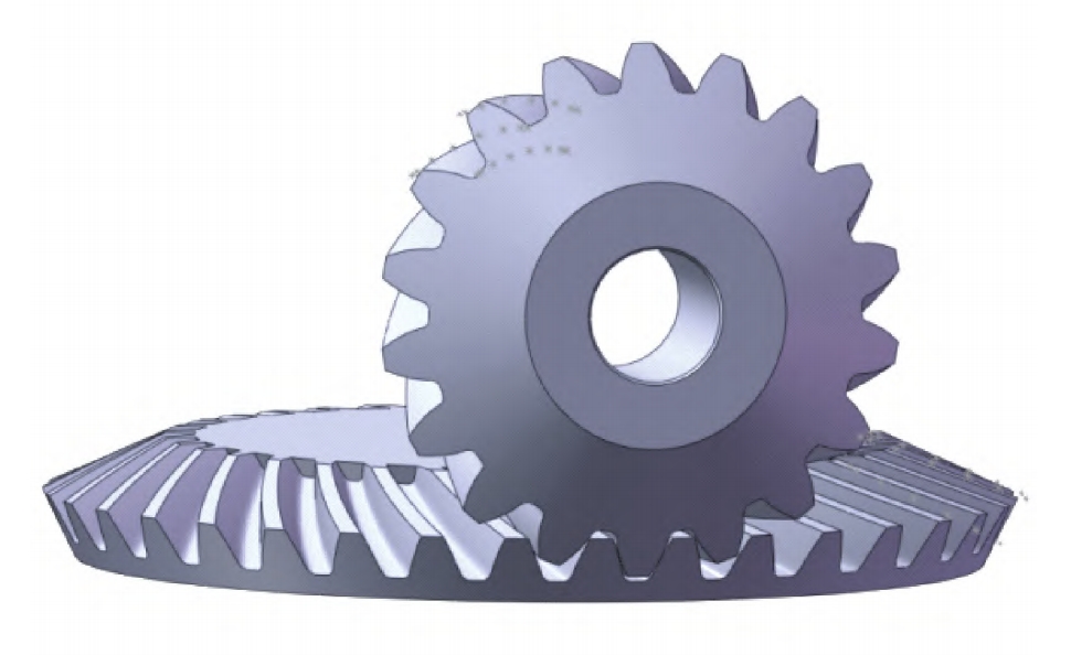
Spiral bevel gears play a crucial role in mechanical transmission systems, enabling power transfer between intersecting or staggered shafts. They are widely used in various industries such as automotive, aerospace, and marine due to their advantages of smooth transmission, high load-carrying capacity, and high transmission efficiency.
1.2 Traditional Manufacturing Methods and Limitations
Traditionally, spiral bevel gears are mainly manufactured by milling processes. However, this method has several drawbacks, including low production efficiency, low material utilization, and the interruption of continuous metal flow lines within the gear, which significantly reduces its strength and service life.
1.3 The Significance of Near-net Rolling Forming Technology
Near-net rolling forming technology offers a promising alternative for spiral bevel gear manufacturing. It not only reduces manufacturing costs but also improves the bending strength of gear teeth by more rational distribution of metal streamline fibers along the tooth profile. This technology has the potential to overcome the limitations of traditional methods and enhance the overall performance of spiral bevel gears.
2. Mathematical Model of Spiral Bevel Gear Tooth Spreading Machining
2.1 Position Motion Relationship in Milling Process
Based on the position motion relationship between the tool and the workpiece during the milling process of spiral bevel gears, a mathematical model of spiral bevel gear tooth spreading machining is constructed. This model provides a theoretical foundation for understanding the gear machining process and predicting the gear tooth geometry.
2.2 Derivation of Gear Die Tooth Surface Equation
Under the condition that the machining parameters of the pinion are known, the equations of the gear die tooth surface are derived using the local synthesis theory. This derivation is essential for accurately modeling the gear tooth surface and ensuring the quality of the manufactured gear.
2.3 Generation of 3D Solid Model
The derived gear die tooth surface equations are used to generate a three-dimensional solid model of the gear. This model can be used for further analysis and simulation, providing a visual representation of the gear geometry and facilitating the design and optimization process.
3. High Temperature Deformation Behavior of Gear Steel 20CrMnTiH
3.1 Experimental Determination of High Temperature Rheological Stress
The high temperature deformation behavior of gear steel 20CrMnTiH is studied through thermal simulation experiments. The experimental setup involves using a Gleeble – 1500D dynamic thermal simulation testing machine to conduct isothermal constant strain rate thermal compression tests on cylindrical bar specimens. The effects of deformation temperature, strain rate, and deformation amount on the rheological stress and microstructure of the steel are investigated.
3.2 Analysis of High Temperature Deformation Mechanics Behavior
- Effect of Deformation Temperature on Rheological Stress: At the same strain rate, the higher the temperature, the lower the corresponding true stress value. This is because at lower temperatures, the work hardening rate is higher, and dynamic recovery is more difficult, resulting in an increase in rheological stress. As the temperature increases, the thermal activation energy promotes atomic jump frequency and vacancy concentration, facilitating dynamic recovery and reducing rheological stress.
- Effect of Strain Rate on Rheological Stress: At the same deformation temperature, the higher the strain rate, the higher the corresponding true stress value. This is because a higher strain rate requires a larger recrystallization driving force, and the core formation probability is low, making recrystallization difficult. Additionally, the work hardening effect increases with the strain rate, resulting in an increase in peak stress and strain before the peak stress appears.
3.3 Establishment of High Temperature Deformation Steady State Rheological Stress Model
Based on the experimental results, a high temperature deformation steady state rheological stress model of gear steel 20CrMnTiH is established. This model is embedded into the DEFORM – 3D finite element analysis software for further numerical simulations of the spiral bevel gear rolling forming process.
4. Numerical Simulation of Spiral Bevel Gear Rolling Forming Based on Local Induction Heating
4.1 Mathematical Model of Electromagnetic Induction Heating
The electromagnetic induction heating process is described by Maxwell’s equations, which include the curl equations for the electric and magnetic fields and the divergence equations for the electric displacement and magnetic induction. The relationship between the electric and magnetic fields, as well as the effects of temperature on the material properties such as relative permeability and electrical conductivity, are considered in the model.
4.2 Establishment of Finite Element Model for Near-net Rolling Forming
- Finite Element Model of Coil and Blank: The finite element model consists of a coil and a wheel blank. The coil is made of T3 copper and is set as a rigid body, while the wheel blank is made of 20CrMnTiH and is considered as a plastic body. The electromagnetic and thermal properties of the materials are defined, and appropriate boundary conditions are set for the simulation.
- Mesh Generation and Boundary Conditions: The coil and the wheel blank are meshed using hexahedral elements. The coil has 40,000 elements, and the wheel blank has 50,000 elements. The boundary conditions include the specification of the current inflow and outflow surfaces of the coil, as well as the heating surface. The induction heating parameters such as current frequency and density are set according to the experimental requirements.
4.3 Analysis of Blank Stress and Strain during Rolling Forming
- Stress Analysis: During the rolling forming process, the stress distribution in the wheel blank changes. At the initial stage of rolling, the stress is mainly concentrated near the contact area between the die and the blank. As the rolling progresses, the stress distribution expands, and the maximum stress occurs at the tooth root and the contact area between the die and the blank. The stress distribution is affected by factors such as the die feed rate, the blank rotation speed, and the friction coefficient.
- Strain Analysis: The strain in the wheel blank is mainly concentrated in the area in contact with the die teeth. At the initial stage of rolling, the strain near the flower key hole is relatively small, while the strain in the contact area is relatively large. As the rolling progresses, the strain distribution expands, and the maximum strain occurs at the tooth root. The strain distribution is also affected by factors such as the die feed rate, the blank rotation speed, and the friction coefficient.
4.4 Analysis of Metal Flow Law during Rolling Forming
The metal flow law during the rolling forming process is analyzed by observing the deformation of the mesh in the wheel blank. The results show that the metal in the wheel blank flows radially and axially under the action of the die. The metal flow is affected by factors such as the die geometry, the die feed rate, and the blank rotation speed. The deformation of the metal flow is more significant in the area near the tooth root and the tooth tip, and the metal flow is relatively uniform in the area away from the tooth surface.
5. Defect Analysis and Control of Spiral Bevel Gear Rolling Forming
5.1 Defect Analysis of Spline Hole
- Cause of Spline Hole Damage: During the rolling forming process, the spline hole of the wheel blank is damaged due to the radial load exerted by the die and the rotation of the wheel blank. The damage is caused by the plastic deformation of the spline hole and the flower key, which leads to the misalignment of the die marks on the wheel blank and the formation of tooth surface folding defects.
- Control Strategy of Spline Hole Damage: Local induction heating is used to control the damage of the spline hole. By creating a temperature gradient in the wheel blank, the rigidity of the inner hole is increased, and the plastic deformation of the spline hole and the flower key is reduced. The numerical simulation and experimental results show that local induction heating can effectively control the damage of the spline hole and improve the quality of the rolled gear.
5.2 Defect Analysis of Roll-rolled Forming Wheel Tooth Surface
- Folding Defect Formation Mechanism: The folding defect of the roll-rolled forming wheel tooth surface is caused by the extrusion of the material on the tooth surface to the tooth root during the rolling process. This is due to the interaction between the die and the wheel blank, which causes the material to flow in an uneven manner and form folds at the tooth root.
- Control Strategy of Folding Defect: The folding defect of the roll-rolled forming wheel tooth surface is controlled by optimizing the geometry of the wheel blank and the process parameters. The experimental results show that when the initial diameter of the large end of the conical wheel blank is 61mm, the tooth shape of the forming wheel is fully filled and the tooth surface folding is less. Additionally, a multi-objective response surface optimization method is used to further optimize the process parameters, and the results show that the optimal process parameters can effectively reduce the tooth surface folding height and improve the quality of the rolled gear.
5.3 Defect Analysis of Tooth Tip of Roll-rolled Forming Wheel
- Tooth Tip Defect Formation Mechanism: The tooth tip defect of the roll-rolled forming wheel is caused by the uneven flow of the material in the radial and axial directions during the rolling process. This is due to the influence of factors such as the die geometry, the die feed rate, and the blank rotation speed, which cause the material to accumulate at the tooth tip and form a bulge or a folding defect.
- Control Strategy of Tooth Tip Defect: The tooth tip defect of the roll-rolled forming wheel is controlled by optimizing the shape of the wheel blank and the die structure. The material compensation coefficient k is introduced to optimize the shape of the wheel blank, and the simulation results show that the effective height of the tooth heel – end and toe – end of the optimized design increases by about 1mm. Additionally, the arc trimming at the tooth root position of the die is deepened to make the roll forming wheel reach its theoretical height, providing a margin for machining to remove the rabbit ear defect.
6. Experimental Research and Verification
6.1 Design of Rolling Experiment Platform
The rolling experiment platform is designed to verify the feasibility and effectiveness of the proposed rolling forming process and quality control strategies. The platform consists of a rolling machine, an induction heating device, a lubrication system, and a measurement system. The rolling machine is used to perform the rolling forming process, the induction heating device is used to heat the wheel blank, the lubrication system is used to lubricate the die and the wheel blank, and the measurement system is used to measure the quality of the rolled gear.
6.2 Experimental Process and Results
The experimental process involves preparing the wheel blank, setting the process parameters, heating the wheel blank using the induction heating device, performing the rolling forming process using the rolling machine, and measuring the quality of the rolled gear using the measurement system. The experimental results show that the proposed rolling forming process and quality control strategies can effectively improve the quality of the rolled gear, reducing the tooth surface folding height, increasing the effective height of the gear teeth, and improving the overall performance of the spiral bevel gear.
7. Conclusion and Outlook
7.1 Research Achievements
This research has achieved several important results in the field of spiral bevel gear near-net rolling forming technology. These include the construction of a mathematical model of spiral bevel gear tooth spreading machining, the study of the high temperature deformation behavior of gear steel 20CrMnTiH, the numerical simulation of spiral bevel gear rolling forming based on local induction heating, the defect analysis and control of spiral bevel gear rolling forming, and the experimental research and verification of the proposed methods.
7.2 Future Research Directions
Despite the achievements of this research, there are still some areas that require further investigation. These include the optimization of the rolling process parameters to further improve the quality of the rolled gear, the study of the long-term performance and reliability of the rolled gear, and the exploration of new materials and manufacturing processes for spiral bevel gears. Future research should focus on these areas to further enhance the manufacturing quality and performance of spiral bevel gears.
| Section | Summary |
|---|---|
| Introduction | Spiral bevel gears are important in mechanical transmission. Traditional milling has limitations. Near-net rolling forming technology is promising. |
| Mathematical Model | Based on milling process, a model for tooth spreading machining is constructed. Gear die tooth surface equation is derived and 3D solid model is generated. |
| High Temperature Deformation | Thermal simulation experiments study 20CrMnTiH steel. Effects of temperature and strain rate on rheological stress are analyzed. A model is established. |
| Numerical Simulation | Electromagnetic induction heating model is described. Finite element model for near-net rolling forming is established. Stress, strain, and metal flow are analyzed. |
| Defect Analysis and Control | Spline hole, tooth surface, and tooth tip defects are analyzed. Control strategies for each defect are proposed. |
| Experimental Research and Verification | A rolling experiment platform is designed. The experimental process and results show the effectiveness of the proposed methods. |
| Conclusion and Outlook | Research achievements are summarized. Future research directions are identified. |