
1. Introduction
Spiral bevel gears play a crucial role in mechanical transmission systems. They are widely used in various fields such as automobiles, construction machinery, energy, aerospace, and steel rolling machinery due to their excellent characteristics like high load-carrying capacity, high transmission efficiency, and smooth motion. However, in high-speed operation, spiral bevel gears may encounter problems such as impact and vibration, and when higher load-carrying capacity is required, new challenges are posed to the tooth surface contact length. Logarithmic spiral bevel gears have emerged as a new type of gear to address these issues, enabling more stable motion transmission and greater load-carrying capacity, making them particularly suitable for high-speed and heavy-duty transmission systems.
In modern engineering design, computer-aided design software has greatly facilitated the modeling, analysis, and optimization of spiral bevel gear structures. Many scholars have adopted different software and methods for modeling and analyzing spiral bevel gears. For example, some have used MATLAB to explore the formation principle of the tooth surface of logarithmic spiral bevel gears and established the tooth surface of equal-height teeth logarithmic spiral bevel gears. Others have proposed three-dimensional parameterized modeling methods based on Boolean difference operations and implemented them using secondary development tools. There are also those who have used software like Pro/E to establish three-dimensional models of logarithmic spiral bevel gears. These studies have demonstrated that using modern advanced software to analyze logarithmic spiral bevel gears is a reliable and effective method in engineering.
This study focuses on the design and mechanical analysis of logarithmic spiral bevel gears using Solidworks software. The aim is to establish a parameterized model, conduct motion analysis, and perform finite element analysis to ensure the strength and reliability of the designed gears and provide valuable references for engineering applications.
2. Logarithmic Spiral Bevel Gear Structure Design
2.1 Gear Material Properties
The material selected for the logarithmic spiral bevel gear is a P91 chromium-molybdenum alloy heat-resistant steel forging. The main chemical components of this material include elements such as carbon, silicon, manganese, chromium, and molybdenum. The P91 alloy exhibits several desirable properties, including high high-temperature strength, creep resistance, oxidation resistance, and corrosion resistance. Compared to carbon steel, the P91 alloy has higher strength and toughness. The specific material property parameters are presented in Table 1.
| Elastic Modulus/(N/mm) | Poisson Ratio | Shear Modulus/(CN·mm²) | Mass Density/(kg/m³) | Tension Strength/MPa | Yield Strength/MPa | Thermal Expansion Coefficient K |
|---|---|---|---|---|---|---|
| 210000 | 0.28 | 79000 | 7700 | 723.8256 | 620.422 | 0.0000013 |
2.2 Gear Geometric Structure Parameters
Using Solidworks as a secondary development platform and combining it with C language programming, a program named GearTeq was developed to automatically generate a parameterized model of the logarithmic spiral bevel gear. The dimension-driven parameterization method was employed, which allows for the rapid creation of a new gear when basic parameters such as gear module, number of teeth, and pressure angle are changed. The parameters used in the GearTeq program for parameterized modeling are listed in Table 2.
| Parameter Name | Parameter Symbol | Input Type |
|---|---|---|
| Number of Teeth | z | Interface Input |
| Large End Module | m | Interface Input |
| Tooth Width/mm | b | Interface Input |
| Addendum Coefficient | ha | Interface Input |
| Clearance Coefficient | c’ | Interface Input |
| Working Tooth Height/mm | h | h = m·(2ha + c’) |
| Shaft Angle/(°) | ∑ | 90 |
| Helix Angle/(°) | β | Interface Input |
| Index Circle Diameter | d | – |
| Cone Angle/(°) | δ | δ = atan(z/∑) |
| Outer Diameter | d₁ | d₁ = d + 2h·cosδ |
By inputting the relevant parameters through the GearTeq program’s input interface, the specific geometric parameters of the spiral bevel gear can be obtained. For example, when the number of teeth z is set to 18 and 36 for the pinion and gear respectively, the geometric parameters are as shown in Table 3.
| Name | Parameter Symbol | Pinion | Gear |
|---|---|---|---|
| Gear Basic Parameters | – | – | – |
| Number of Teeth | z | 18 | 36 |
| Large End Module/mm | m | – | – |
| Tooth Width/mm | b | – | – |
| Addendum Coefficient | ha | – | – |
| Clearance Coefficient | c’ | – | – |
| Working Tooth Height/mm | h | – | – |
| Shaft Angle/(°) | ∑ | – | – |
| Helix Angle/(°) | β | – | – |
| Helix Direction | – | Right-handed | Left-handed |
| Geometric Parameter Values | – | – | – |
| Index Circle Diameter/mm | d | 45 | 90 |
| Cone Angle/(°) | δ | 26.5651 | 63.3 |
| Crown Distance/mm | R | 6.38 | 6.35 |
| Mounting Distance/mm | P | 50.77206 | 50.27422 |
| Addendum Height/mm | ha | 2.90322 | 2.54 |
| Total Tooth Height/mm | h | 4.79552 | 5.60832 |
| Dedendum Height/mm | hf | 1.89484 | 3.01752 |
| Apex Cone Angle/(°) | δa | 30.3475 | 50.3324 |
| Root Cone Angle/(°) | δt | 24.4435 | 42.328 |
2.3 Gear Contact Stress
The contact stress formula for gear tooth surfaces is given by:
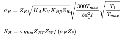
where σH is the contact stress on the tooth surface, T1 is the working torque of the pinion, b is the tooth width, d1 is the large end index circle diameter of the pinion, ZE is the elastic coefficient, KA is the service coefficient, KV is the dynamic load coefficient, KHβ is the load distribution coefficient, ZR is the surface condition coefficient, I is the geometric coefficient of tooth surface contact strength, SH is the contact strength safety coefficient, σHlim is the contact fatigue limit, ZNT is the contact fatigue strength life coefficient, ZW is the work hardening coefficient, and Zθ is the temperature coefficient.
The parameter values used for the logarithmic spiral bevel gear in this study are presented in Table 4.
| Parameter Meaning | Parameter Value | Parameter Meaning | Parameter Value |
|---|---|---|---|
| Elastic Coefficient | 189.8 | Stress Cycle Coefficient | 1.97 |
| Overload Coefficient | 1.0 | Hardness Ratio Coefficient | 1.0 |
| Dynamic Load Coefficient | 1.0 | Tooth Surface Contact Strength Geometric Coefficient | 1.23 |
| Contact Strength Calculated Load Distribution | 1.8 | Size Coefficient | 4.1 |
| Temperature Coefficient | 0.85 | Surface Condition Coefficient | 0.85 |
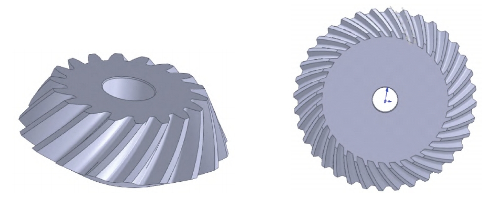
2.4 Logarithmic Spiral Bevel Gear Structure Design
Based on the dimension-driven parameterization modeling method and the given values (Table 3), a digital model of the logarithmic spiral bevel gear was established using Solidworks software. To evaluate its strength and rationality, the strength was checked using the gear theoretical contact stress formulas (1) and (2), and the meshing and motion analysis of the pinion and gear were carried out to verify the rationality of the designed spiral bevel gear structure.
3. Finite Element Model Establishment and Mechanical Analysis
3.1 Finite Element Model Mesh Division
In the Solidworks Simulation module, the mesh division quality affects the simulation calculation speed and the accuracy of the analysis results. For the logarithmic spiral bevel gear in this study, a larger mesh size was used for the overall mesh division, and a more refined mesh division was performed on the gear meshing part to improve the mesh division accuracy and the analysis result accuracy. The mesh type used was a solid mesh, the mesh quality was set to high, and the mesh unit size was set to 1.5 mm. A total of 158106 units and 234797 nodes were generated.
3.2 Static Stress Analysis
In the static stress analysis, the rotation freedom around the axis of the driving pinion was retained, and the other freedoms were constrained. Torque loads were applied to the driving pinion, and the driven gear was fully constrained. Torques of 50, 100, 150, and 200 N·m were applied to the driving pinion respectively, and the friction coefficient was set to 0.1 for stress analysis.
It can be seen that when torques of 50, 100, 150, and 200 N·m are applied to the gear respectively, the corresponding maximum stresses are 469.6, 644.2, 1227, and 4704 MPa respectively. The maximum stress is mainly concentrated on the gear meshing part, as well as the tooth root and tooth top parts, which are more prone to deformation and damage.
To study the contact strength of the logarithmic spiral bevel gear, the analysis of the gear tooth surface contact stress was focused on. Therefore, the stress measurement on the meshing part was carried out using the probe command in Solidworks.
The maximum stress, minimum stress, and average stress are presented in Table 5.
| Driving Pinion Applied Torque/(N·m) | Maximum Stress/MPa | Minimum Stress/MPa | Average Stress/MPa |
|---|---|---|---|
| 50 | 420.20 | 0.1769 | 38.98 |
| 100 | 644.20 | 0.2503 | 70.73 |
| 150 | 1227.00 | 0.3677 | 104.10 |
| 200 | 4704.00 | 0.4542 | 138.50 |
According to the stress analysis results in Table 5, when a torque of 50 N·m is applied to the driving pinion, the maximum stress at the gear meshing place is 420.2 MPa, which is less than the yield strength of the material (620.422 MPa). When a torque of 100 N·m is applied, the maximum stress at the gear meshing place is 644.2 MPa, slightly exceeding the yield limit of the material, and the gear undergoes slight deformation. However, when torques of 150 and 200 N·m are applied, the maximum stresses at the gear meshing place reach 1227 and 4704 MPa respectively, far exceeding the yield limit of the material, resulting in severe deformation of the gear.
Therefore, the range of torque between 50 and 100 N·m needs to be refined to find the optimal value so that the maximum stress at the meshing part of the spiral bevel gear does not exceed the yield strength of the material and no permanent deformation or rupture occurs within the load-bearing range. In the static stress analysis, torques of 60, 60.5, 61, and 65 N·m were applied to the driving pinion respectively, and the friction coefficient was set to 0.1. The stress analysis results
It can be seen that when torques of 60, 60.5, 61, and 65 N·m are applied to the driving pinion respectively, the maximum stresses at the meshing place are 511, 498, 2640, and 736.2 MPa respectively. The maximum stress is still mainly concentrated on the gear meshing part and the tooth root position. To further study the contact strength of the logarithmic spiral bevel gear, a more detailed stress analysis on the meshing part was carried out using the probe command.
The logarithmic spiral bevel gear has relatively large axial and radial forces, resulting in a more complex stress distribution. When the torque is between 60 and 65 N·m, the stress on the tooth top, tooth root, and meshing part of the gear may change, causing stress concentration in local areas and the appearance of local maximum stress. When the torque is 100 N·m, the stress situation changes, and the local stress is dispersed to other parts, resulting in a change in the position and magnitude of the local maximum stress. The situation where the local maximum stress at a torque of 60 to 65 N·m exceeds that at a torque of 100 N·m is presented in Table 6.
| Driving Pinion Applied Torque/N·m | Maximum Stress/MPa | Minimum Stress/MPa | Average Stress/MPa |
|---|---|---|---|
| 60 | 456.90 | 0.2033 | 43.75 |
| 60.5 | 447.00 | 0.2095 | 44.78 |
| 61 | 2640.00 | 0.1388 | 43.40 |
| 65 | 736.20 | 0.2172 | 48.98 |
By comparing the results in Table 6, it can be seen that when torques of 60 and 60.5 N·m are applied to the driving pinion, the maximum stresses at the meshing part are 456.9 and 447.0 MPa respectively, both less than the yield limit of the material (620.422 MPa). However, when torques of 61 and 65 N·m are applied, the maximum stresses at the meshing part reach 2640 and 736.2 MPa respectively, exceeding the yield limit of the material, resulting in severe deformation and damage of the gear. Therefore, to ensure the normal and reliable meshing of the logarithmic spiral bevel gear, the applied torque should not exceed 60.5 N·m.
3.3 Contact Strength Check
When a torque T1=60.5N•m is applied to the driving pinion and T1max≈T1, the allowable contact stress on the gear tooth surface can be calculated as 484 MPa. According to the results in Table 6, in the working state, the maximum contact stress on the gear tooth surface is 447 MPa, which does not exceed the allowable contact stress. Therefore, when the torque applied to the driving pinion does not exceed 60.5 N·m, it is within the allowable stress range and meets the strength requirements.
3.4 Strain Analysis
In the static stress analysis, torques of 50, 100, 150, and 200 N·m were applied to the driving pinion respectively, and the friction coefficient was set to 0.1 for displacement analysis.
The displacement values of the meshing part of the logarithmic spiral bevel gear obtained through simulation are presented in Table 7.
| Displacement/mm | Applied Torque/(N·m) | |||
|---|---|---|---|---|
| 50 | 100 | 150 | 200 | |
| Maximum | 0.2075 | 0.1815 | 0.1624 | 0.1384 |
| Minimum | 1×10⁻³⁰ | 1×10⁻³⁰ | 1×10⁻³⁰ | 1×10⁻³⁰ |
From Table 7, the following conclusions can be drawn:
- As the torque increases, the maximum displacement of the logarithmic spiral bevel gear gradually increases, but the growth rate gradually slows down. In a certain range, the maximum displacement decreases with the increase of torque.
- The reason why the maximum displacement of the logarithmic spiral bevel gear decreases with the increase of torque in a certain range is that as the torque increases, the load on the gear increases, but the deformation of the gear has not reached its material limit. Therefore, although the degree of deformation increases, the growth rate gradually slows down. When the torque further increases, the deformation of the gear will reach its material limit, and the maximum displacement of the gear will increase sharply until the gear is damaged.
- When a torque is applied to the driving pinion, the tooth top part of the meshing gear is more prone to deformation.
4. Conclusions
In this study, a logarithmic spiral bevel gear made of P91 chromium – molybdenum alloy forged steel was selected. Using the secondary development platform of Solidworks and C language programming, a parameterized table of the logarithmic spiral bevel gear was established. By inputting corresponding parameters, a bevel gear was automatically created using the GearTeq program. Based on the dimension – driven parameterization modeling method, a pair of three – dimensional models of logarithmic spiral bevel gears with 18 and 36 teeth respectively were quickly created, and the meshing and motion simulation was carried out to verify the rationality of the gear structure. The Simulation module of Solidworks was used to analyze the stress and strain at the meshing part of the spiral bevel gear. The results show that the torque applied to the driving pinion should not exceed 60.5 N·m. At this time, the maximum stress at the gear meshing part is 456.9 MPa, which is less than the yield strength of the material (620.422 MPa), so the logarithmic spiral bevel gear will not undergo plastic deformation. The gear contact strength was checked using the gear theoretical contact stress formula, and the results show that it meets the strength requirements within the allowable stress range. Further analysis of the strain at the gear meshing part shows that in a certain range, the maximum displacement of the logarithmic spiral bevel gear decreases with the increase of torque, and the tooth top part of the meshing gear is more prone to deformation.
This research provides a reliable reference and method for the structural design and transmission strength of logarithmic spiral bevel gears, which is of great significance for engineering practices and gear design in related fields. Future research can focus on further optimizing the design parameters and analyzing the performance of logarithmic spiral bevel gears under more complex working conditions.