
Abstract: This article focuses on the cold precision forging process of cylindrical spur gear. Based on the existing process, two new process schemes, “flash hole” (Scheme B) and “diversion groove” (Scheme C), are introduced. Through numerical analysis using Deform – 3D software, it is verified that these two schemes can significantly reduce the forming load and improve the forming quality compared to the traditional closed forging process (Scheme A). The stress values of Schemes B and C are smaller and more evenly distributed. Additionally, an analysis of the forming load with different friction coefficients and upper die descending speeds is conducted, providing a theoretical basis for the selection of actual process parameters.
1. Introduction
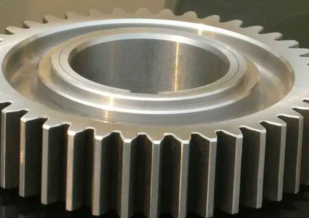
Cylindrical spur gear is widely used in various industries such as aerospace, military, aircraft, and intelligent home appliances as important power transmission and motion components. Cold precision forging of cylindrical spur gear offers several advantages, including high material utilization, high production efficiency, low cost, simple process, high mechanical properties, and good surface quality. However, due to the complex structure of spur gear, difficulties in filling the tooth tip corners, and large forming loads leading to low die life, the development of cylindrical spur gear has been restricted, which are also the key and difficult points to be in actual production and technical research.
2. Establishment of Cylindrical Gear Forming Process
2.1 Traditional Production Process
For the common cylindrical spur gear studied in this article (with basic parameters such as module 2.0, number of teeth 30, tooth width 20mm, and pressure angle 20°), many enterprises still adopt the traditional production process: blanking → heating → upsetting → die forging for blank making → machining → heat treatment. The surface quality of hot-forged parts is poor, and machining is required to ensure accuracy. The spur gear tooth profile is completed by cutting, resulting in low material utilization.
2.2 Cold Precision Forging Process Schemes
- Scheme A: A common closed forging process at room temperature without a flash design.
- Scheme B: A flash groove with a diameter of ϕ6mm is opened on the central axis of the upper die to reduce the forming load.
- Scheme C: A diversion groove is opened at the tooth tip of the cylindrical spur gear to ensure full filling at the tooth tip corners.
3. Finite Element Numerical Analysis
3.1 Establishment of Finite Element Models for Three Processes
Using Deform – 3D software, a quarter model is adopted for numerical simulation due to the rotational symmetry of the cylindrical spur gear to improve computational efficiency. The basic parameters such as blank size, friction coefficient, forming rate, number of meshes, blank and die temperature, and spur gear material are shown in Table 1.
| Process Parameters | Blank Size (mm) | Die and Blank Temperature | Forming Rate (m/s) | Number of Meshes | Gear Material | Friction Coefficient |
|---|---|---|---|---|---|---|
| Numerical | Φ50×38.5 | 20°C | 1 | 100000 | Steel – AISI – 4120 | 0.1 |
The finite element models (omitted here as it is difficult to describe accurately in text).
3.2 Analysis of Finite Element Results for Three Processes
- Forming Load Comparison: The forming load magnitudes of the three process schemes are . The maximum forming load of Scheme A is 1,500kN, that of Scheme B is 1,393kN, and that of Scheme C is 1,397kN. Although the diameters of the flash hole in Scheme B and the depth of the diversion groove in Scheme C are small (only 6mm and 0.5mm respectively), compared to Scheme A, the maximum forming load of both Schemes B and C still decreases by more than 100kN, indicating their significant effects on reducing the forming load.
- Gear Center and Tooth Machining: After forming, both Schemes B and C require machining of spur gear center and teeth, and the choice should be made considering the gear’s own structure and the original process. In this article, Scheme C is selected after comprehensive consideration.
3.3 Analysis of the Forming Process of Three Processes
In the stress – strain field during the forming process of the cylindrical spur gear:
- Process Stages: In the first 50% of the stroke, it is mainly an upsetting process with almost no stress – strain. At 50%, the forming of spur gear teeth begins, and stress – strain increases. As the metal deformation intensifies, spur gear teeth are gradually formed, and stress – strain reaches the maximum. The stress is mainly concentrated at spur gear teeth, and the maximum strain is basically at the tooth tip, indicating that the deformation at the tooth tip is the most severe and difficult, and the forming quality is the most difficult to guarantee, which is consistent with the actual situation.
- Stress Comparison: The maximum stress of Scheme A is about 5.5, while that of Schemes B and C is about 3. Schemes B and C can effectively reduce the maximum stress, prevent stress concentration, and improve spur gear life. At the same time, for all process schemes, the stress is mainly concentrated at spur gear teeth with a relatively uniform distribution, indicating that the residual stress of the forged part is small and the quality is good.
4. Process Parameter Optimization
4.1 Selection of Process Parameters
- Upper Die Descending Speed: It reflects the downward displacement of the upper die per unit time. An excessive speed can cause severe deformation of the forging in a short time, resulting in a sharp increase in the forming load, affecting the die life and easily causing cracking of the forging and affecting its quality. A too low speed affects production efficiency. Considering the actual production situation, the upper die descending speeds of 1mm/s, 5mm/s, and 10mm/s are selected.
- Friction Coefficient: In spur gear forging, friction between the upper and lower dies and the forging is inevitable. The use of lubricants is very important in actual production. Referring to theoretical data and combining practical experience, friction coefficients of 0.1, 0.2, and 0.3 are selected.
4.2 Analysis of Parameter Optimization Results
As shown in Table 2, the upper die descending speed and friction coefficient have a significant impact on the maximum forming load. Among the nine groups of experiments, the maximum forming load in group i is 2,070kN, and the minimum in group a is 1,489kN, with a maximum load difference of 581kN and a decrease of 28%. The research range of the descending speed is from 1 to 10mm/s, and that of the friction coefficient is from 0.1 to 0.3, providing a theoretical basis for parameter selection. Considering the actual situation, a friction coefficient of 0.2 and a descending speed of 1mm/s are selected, with a required load of 1,654kN, which meets the actual production requirements.
| Parameter Combination Sequence | Friction Coefficient | Upper Die Descending Speed (mm/s) | Maximum Forming Load (kN) |
|---|---|---|---|
| a | 0.1 | 1 | 1489 |
| b | 0.1 | 5 | 1652 |
| c | 0.1 | 10 | 1688 |
| d | 0.2 | 1 | 1654 |
| e | 0.2 | 5 | 1773 |
| f | 0.2 | 10 | 1862 |
| g | 0.3 | 1 | 1718 |
| h | 0.3 | 5 | 1873 |
| i | 0.3 | 10 | 2070 |
5. Conclusions
- Significant Role of New Schemes: On the basis of the existing production process of cylindrical spur gear, the “flash hole” Scheme B and the “diversion groove” Scheme C are added. Through Deform – 3D finite element analysis, it is verified that opening “flash holes” and “diversion grooves” has a significant effect on reducing the forming load.
- Improvement of Forming Quality: Through finite element numerical simulation, the changes in the stress – strain fields of the three process schemes are analyzed, clarifying the laws of cold precision forging of cylindrical spur gear. It is analyzed that Schemes B and C can effectively reduce the stress value of spur gear and make the stress distribution uniform, reducing the impact of stress concentration and residual stress on the forming quality of spur gear.
- Theoretical Basis for Parameter Selection: The forming load distribution laws and ranges when the friction coefficient is from 0.1 to 0.3 and the upper die descending speed is from 1 to 10mm/s are obtained, providing a theoretical basis for the actual selection of main process parameters.
In summary, this research provides valuable insights and theoretical support for the cold precision forging process of cylindrical spur gear, which is beneficial for improving the production efficiency and quality of cylindrical spur gear.
6. Future Research Directions
- Advanced Material Studies: Investigate the use of new materials for spur gear that can further improve mechanical properties and reduce forming loads. For example, study the application of advanced alloys or composites in spur gear manufacturing.
- Multi – Objective Optimization: Consider multiple objectives simultaneously, such as minimizing forming load, maximizing spur gear quality, and reducing production costs. Develop more comprehensive optimization algorithms and models to achieve better overall performance.
- Process Simulation Refinement: Improve the accuracy of the numerical simulation process by considering more detailed physical phenomena, such as microstructural changes during forging and the influence of lubricant film thickness on friction.
- Experimental Validation: Conduct more extensive experimental studies to validate the theoretical results obtained from numerical simulations. This includes performing actual forging experiments with different process parameters and comparing the results with the predicted values.
7. Industrial Applications and Significance
- Automotive Industry: Cylindrical spur gear is widely used in automotive transmissions. The improved cold precision forging process can lead to higher quality spur gear with better mechanical properties, reducing wear and tear and improving the overall performance and reliability of the transmission system.
- Aerospace Industry: In aerospace applications, where high precision and reliability are crucial, the optimized forging process can produce spur gear that meet strict quality standards, ensuring the smooth operation of various mechanical systems in aircraft.
- Manufacturing Efficiency Improvement: The research findings can be applied in manufacturing plants to optimize the production process of spur gear. By reducing forming loads, die life can be extended, and production costs can be lowered, thereby increasing the competitiveness of the manufacturing enterprise.
8. Challenges and Solutions in Implementation
- Process Complexity: The introduction of new process schemes such as “flash hole” and “diversion groove” may increase the complexity of the manufacturing process. Solutions include providing detailed training to operators and developing standardized operating procedures to ensure consistent quality.
- Cost Considerations: Implementing new processes may involve additional costs for equipment modification and process optimization. Manufacturers can conduct cost – benefit analyses to determine the feasibility of implementing the new processes and explore ways to reduce costs, such as sharing equipment among different product lines.
- Quality Control: Ensuring consistent quality of the forged spur gear is a challenge. Advanced quality control techniques such as non – destructive testing methods and in – process monitoring systems can be employed to detect any defects early and take corrective actions.
9. Comparison with Other Gear Manufacturing Processes
- vs. Machining: Compared to traditional machining processes, cold precision forging offers higher material utilization and better mechanical properties. Machining typically involves removing a significant amount of material, resulting in waste, while forging shapes spur gear by plastic deformation, maintaining the integrity of the material’s microstructure.
- vs. Hot Forging: Although hot forging can also achieve certain forming of spur gear, cold precision forging has the advantage of better surface quality and more precise dimensional control. Hot forging may cause surface oxidation and dimensional inaccuracies due to the high temperature involved.
10. Summary of Key Findings
- Forming Load Reduction: The “flash hole” and “diversion groove” process schemes significantly reduce the forming load, with a maximum reduction of over 100kN compared to the traditional process.
- Improved Forming Quality: Schemes B and C result in smaller and more evenly distributed stress values, indicating better forming quality and reduced stress concentration.
- Parameter Optimization: The analysis of friction coefficients and upper die descending speeds provides a theoretical basis for selecting optimal process parameters, with a maximum load difference of 581kN and a 28% decrease within the studied parameter ranges.
The research on the cold precision forging process of cylindrical spur gear presented in this article has important theoretical and practical significance, and further research and development in this field are expected to bring more benefits to the manufacturing industry.