
Abstract: This article focuses on the analysis of the dynamic load characteristics of spur gear with high contact ratios. By comparing with ordinary spur gear, the differences in meshing stiffness, dynamic response, and dynamic load coefficients are explored. Through finite element analysis and dynamic modeling, the influence of various factors such as rotational speed and manufacturing errors on the performance of high contact ratio spur gear is studied. The results show that high contact ratio spur gear has better performance in terms of stability and dynamic load resistance, providing a theoretical basis for the design and application of such spur gear.
1. Introduction
Gear transmission is an essential part of mechanical transmission systems, widely used in aerospace, automotive, and other industries due to its advantages of smooth transmission, high power transmission, and long working life. With the continuous development of industrial capabilities and the increasing demand for high-speed, efficient, and lightweight mechanical systems, traditional ordinary spur gear face challenges. High contact ratio (HCR) spur gear, which have a contact ratio greater than 2, have emerged as a solution. These gear has several advantages over ordinary spur gear with a contact ratio between 1 and 2. They can increase the number of meshing tooth pairs, improve the load-carrying capacity of spur gear, and reduce vibration and noise, making them suitable for high-speed and heavy-load applications. The vibration characteristics during meshing directly affect the dynamic load performance of the entire system. Therefore, studying the dynamic characteristics of HCR spur gear systems is of practical significance.
2. Literature Review
Previous research on HCR spur gear has mainly focused on their design and load-carrying capacity. For example, Rajesh et al. optimized the design of HCR spur gear using a variable tooth thickness hob cutter and analyzed the contact stress. Zhang Lin conducted a multi-objective constraint analysis on the parameters of external and internal meshing gear and analyzed the gear stress distribution using finite element transient dynamics. Li Fajia et al. provided a formula for calculating the tooth root bending strength of HCR spur gear and verified it experimentally. Franulovic et al. studied the influence of pitch deviation on the load-carrying capacity of HCR spur gear. Hussein et al. designed non-involute HCR gears with improved load-carrying capacity. Marimuthu et al. analyzed asymmetric HCR spur gear and their load-carrying capacity. Sanchez et al. studied an approximate calculation equation for meshing stiffness and load distribution applicable to HCR spur gear and verified it using finite elements. Pedrero et al. studied the influence of tooth profile modification on gear load distribution. Dogan compared the dynamic tooth root bending stress and dynamic characteristics of ordinary and HCR spur gear.
Regarding the research on dynamic load coefficients, Su Jipeng et al. considered transmission errors to establish a six-branch herringbone gear transmission system and solve its dynamic load coefficient. Bao Heyun et al. considered factors such as tooth surface friction to establish a dynamics model of a helicopter transmission system and compare the dynamic load coefficients of each stage. Hu Shengyang et al. considered the flexibility of the inner ring gear to analyze the variation law of the dynamic load coefficient of different ring gear structures. Li Mengfei studied the dynamic load coefficient of ultra-high-speed gears based on the finite element method. Li Chunming et al. analyzed the influence of tooth profile modification and spoke stiffness on the dynamic load coefficient of spur gear under high-speed and heavy-load working conditions.
However, compared with the research on ordinary spur gear, the research on the dynamic characteristics and dynamic load coefficients of HCR spur gear still needs to be further explored. This article aims to fill this gap by establishing a dynamics model of HCR spur gear considering the influence of time-varying meshing stiffness and error excitation, solving the dynamics equation, comparing the dynamic responses of LCR and HCR spur gear, and solving the dynamic load coefficient of HCR spur gear.
3. Gear System Dynamics Model Building
3.1 Gear Analysis Model Building
The research objects in this article are a pair of HCR spur gear and a pair of LCR spur gear with the same basic parameters for comparison. The parameters of the two pairs of gear is shown in Table 1 and Table 2. The HCR spur gear is processed by “modification” to increase the addendum coefficient and reduce the pressure angle, resulting in a contact ratio greater than 2. During operation, the LCR spur gear experience a “double-tooth – single-tooth – double-tooth” meshing change process, while the HCR spur gear experience a “three-tooth – double-tooth – three-tooth – double-tooth – three-tooth” change process, with an increased number of meshing tooth pairs.
| Table 1: Parameters of LCR Spur Gear | |||
|---|---|---|---|
| Parameter | Value | Parameter | Value |
| Module (mm) | 2.3 | Contact Ratio | 1.707 |
| Number of Teeth (z1/z2) | 33/46 | Center Distance (mm) | 90.85 |
| Pressure Angle (°) | 20 | Pinion Modification Coefficient | 0 |
| Tooth Width (mm) | 29/25 | Gear Modification Coefficient | 0 |
| Addendum Coefficient | 1 | Output Rotational Speed (r/min) | 800 |
| Clearance Coefficient | 0.25 | Input Torque (N·m) | 100 |
| Table 2: Parameters of HCR Spur Gear | |||
|---|---|---|---|
| Parameter | Value | Parameter | Value |
| Module (mm) | 2.3 | Center Distance (mm) | 91.5 |
| Number of Teeth (z1/z2) | 33/46 | Contact Ratio | 2.14 |
| Pressure Angle (°) | 18 | Pinion Modification Coefficient | 0.3 |
| Tooth Width (mm) | 29/25 | Gear Modification Coefficient | -0.008 |
| Addendum | 3.544/2.996 | Total Tooth Height (mm) | 6.465 |
3.2 Time-Varying Meshing Stiffness Calculation
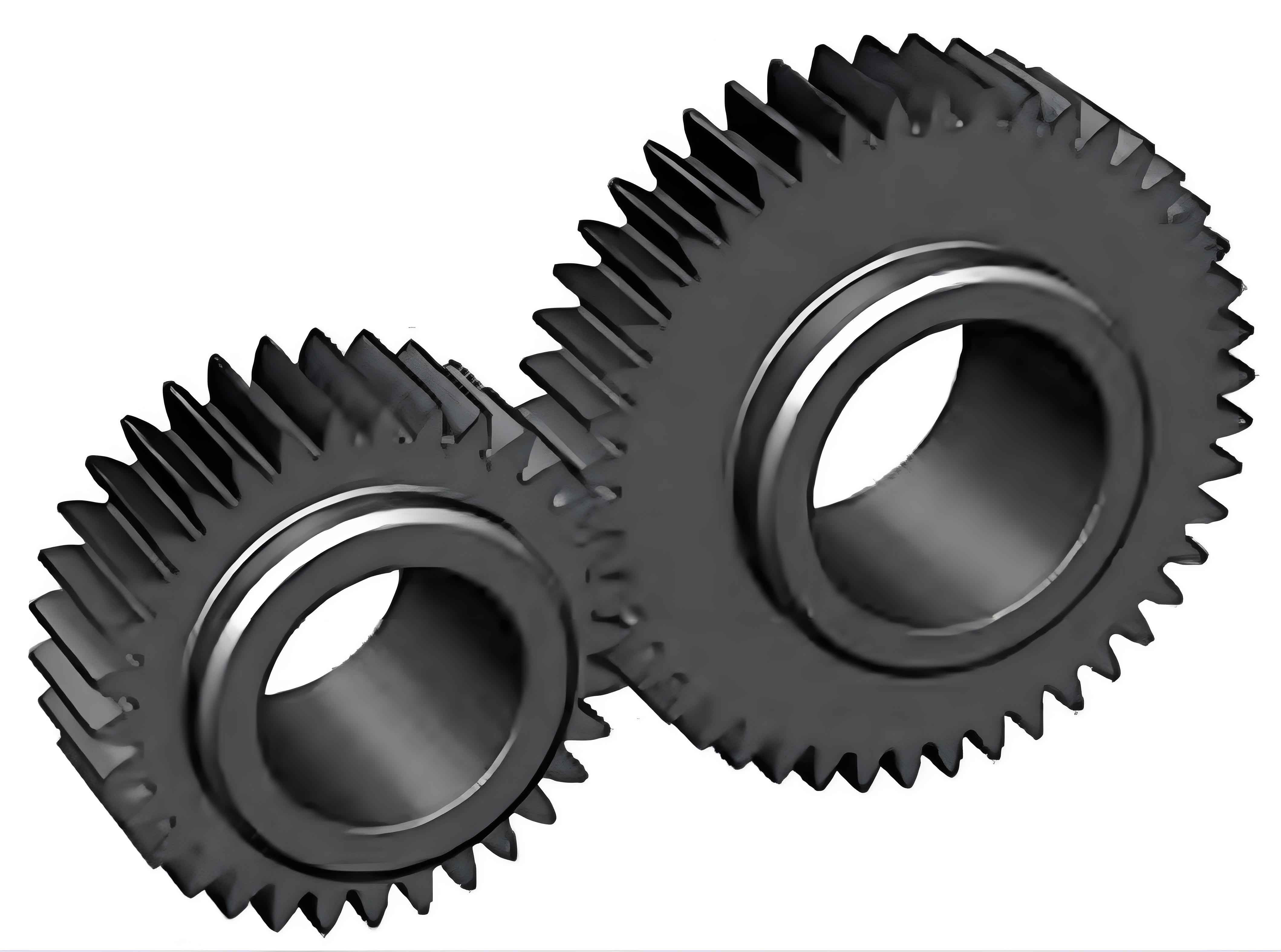
Accurate calculation of time-varying meshing stiffness is essential for dynamic analysis of gear systems. In this article, the finite element method is used to calculate the meshing stiffness of spur gear. The gear material is 20CrMnTiH, and a hexahedral mesh is used for division. The driving gear is set as the target surface, and the driven gear is set as the contact surface. The tooth surface friction coefficient is selected as 0.15, and the mesh in the tooth surface contact area is subdivided. The inner ring of the driven gear is fixed, and a torque is applied to the inner ring of the driving gear. The finite element mesh model . The meshing cycle of the gear is divided into several parts to obtain the meshing state at each moment. According to the gear meshing relationship, the final stiffness Kn is calculated using the formula
Where Fn and μ are the equivalent force and equivalent deformation in the meshing line direction, respectively, and T, θ, and γb are the torque, deformation angle, and base circle radius of the driving gear, respectively. The time-varying meshing stiffness of LCR and HCR spur gears is calculated using the finite element analysis results and the above formula, and the results .
The meshing stiffness curves of LCR and HCR spur gear both show a square wave pattern with alternating magnitudes. For LCR spur gear, during the meshing cycle, the meshing stiffness alternates between double-tooth meshing and single-tooth meshing. The meshing stiffness during double-tooth meshing is approximately 3.62X10^8 N/m, and during single-tooth meshing, it is approximately 2.51X10^8 N/m. The stiffness changes abruptly during the alternation, causing internal stiffness excitation and periodic changes in tooth elastic deformation, resulting in severe vibration and reduced stability of spur gear system. In contrast, for HCR spur gear, the meshing process alternates between three-tooth meshing and double-tooth meshing. The meshing stiffness during three-tooth meshing is approximately 4.62X10^8 N/m, and during double-tooth meshing, it is approximately 3.82X10^8 N/m. During the meshing cycle, the HCR spur gear is always in a multi-tooth bearing contact state, and the stiffness change is weakened when the number of meshing tooth pairs changes. In actual transmission, the reduction of internal stiffness excitation has a positive effect on reducing system vibration and improving gear transmission stability.
3.3 Gear System Dynamics Model
Based on the actual transmission relationship of spur gear, for parts with small mass and large elasticity such as shafts and bearings in spur gear transmission system, they are equivalent to springs, and for parts with large mass and small elasticity such as spur gear, they are equivalent to mass blocks. Thus, a meshing-coupled analysis model of spur gear pairs is obtained . In this model, the input end is defined as P, the output end is defined as Q, and spur gear meshing line direction is defined as the Y direction. Since the specific vibration form of the transmission shaft is not considered, combined equivalent values Kpy, Kq, Cpy, and Cq are used to represent the support stiffness and damping of the transmission shaft, bearing, and box. This model is a two-dimensional plane vibration system. Without considering tooth surface friction, the dynamic meshing force of spur gear is along the meshing line direction, and the driving and driven gear have rotational and translational degrees of freedom along the meshing line direction, totaling 4 degrees of freedom. The generalized displacement vector of the system is .
The torsional and translational displacements of the driving and driven gear will affect the meshing state of spur gears, and their projections on the meshing line can be expressed as
The elastic meshing force Fk and meshing damping force Fc between spur gear teeth during meshing can be expressed as
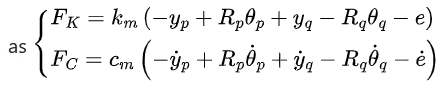
where km is spur gear meshing stiffness, Cm is spur gear meshing damping, and is the error. The dynamic meshing force Fre during gear meshing is Fre=Fk+Fc. Based on the above analysis, the system dynamics model can be expressed as
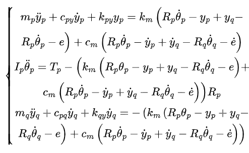
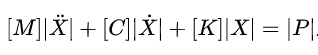
where mp and mq are the masses of the driving and driven gear, respectively, Ip and Iq are the moments of inertia of the driving and driven gear, respectively, cpy and cpq are the translational vibration damping coefficients of the driving and driven gear, respectively, and kpy and kqy are the support stiffnesses of the driving and driven gear, respectively. The matrix form of the equation is
4. Dynamic Characteristics Analysis
4.1 Natural Frequency
Ignoring the external excitation and damping of the system, the undamped free vibration equation of spur gear transmission system can be expressed as Mx+Kx=0. Defining the natural frequency of spur gear system as and the corresponding vibration mode as , the generalized characteristic equation is , where and are the mass matrix and meshing stiffness matrix of spur gear system, respectively. Solving this equation, the natural frequencies of spur gear pairs are obtained as shown in Table 3.
| Table 3: Natural Frequencies of Gear Pairs (Hz) | |||
|---|---|---|---|
| Gear Type | 1st Order | 2nd Order | 3rd Order |
| LCR Spur Gear | 3155 | 4717 | 7484 |
| HCR Spur Gear | 2927 | 4241 | 7232 |
4.2 Bearing Dynamic Load
Using the Newmark – time-domain integration method to solve the model with an input rotational speed of 800 r/min and a load of 100 N for the driving gear, the dynamic loads on each bearing are obtained. The time-domain histories and spectra of the input-end bearing dynamic loads for LCR and HCR spur gear, respectively. The time-domain histories and spectra of the output-end bearing dynamic loads for LCR and HCR spur gear.
In spur gear meshing cycle, there are stiffness incentives and impact incentives when the teeth enter and exit meshing, which cause changes in the system load. The time-domain histories of the input-end bearing dynamic loads for HCR and LCR spur gear change periodically. The amplitude of the input-end bearing dynamic load for LCR spur gear (defined as the maximum value minus the mean value) is 197 N, while for HCR spur gear, it is 66 N, with a significantly reduced fluctuation amplitude. The frequency-domain images of the input-end bearing dynamic loads show that the main frequency components are the meshing frequency and its harmonics. For LCR spur gear, the 4th, 5th, and 6th harmonic components are more obvious, while for HCR spur gear, the 6th harmonic component near the 1st order natural frequency of the system has the largest energy.
Compared with LCR spur gear, the fluctuation range of the output-end bearing dynamic load for HCR spur gear is significantly reduced, and the fluctuation amplitude is decreased by 69.57%, which can significantly reduce the vibration and noise generated during the actual gear transmission process. The spectrum diagrams show that the main frequency components of the output dynamic load for LCR spur gear is the 4th and 5th harmonic components, with the 5th harmonic having the largest energy, while for HCR spur gear, the 6th harmonic has the largest energy, and the meshing frequency and its harmonics are significantly lower than those of LCR spur gear.
4.3 Rotational Speed Influence on Bearing Dynamic Load
In actual operation, the rotational speed of spur gear system is not constant, and it directly affects the frequency components of the internal complex incentives of the system. To analyze the fluctuation of the bearing dynamic load of spur gear system at different rotational speeds, the changes in the bearing dynamic loads of HCR and LCR spur gear in the rotational speed range of 500 – 3000 r/min are calculated .