
Abstract: This article focuses on the hypoid gear processed by the HFT method. It establishes a mathematical model of the hypoid gear drive and analyzes its time-varying meshing characteristics. The research includes deriving tooth surface and root transition surface equations, performing tooth contact analysis, and using finite element analysis to study the effects of load changes. The results provide a basis for understanding the transmission characteristics and dynamic behaviors of hypoid gear.
1. Introduction
Hypoid gear is widely used in various vehicles and machinery due to their advantages such as small size, large transmission ratio, and strong load-carrying capacity. The HFT method is a commonly used processing method in China. However, the complex equations of the theoretical tooth surface and root transition surface make it necessary to accurately model hypoid gear for further research on its meshing and transmission characteristics.
1.1 Research Background
Previous studies have made some progress in hypoid gear modeling and analysis. For example, some studies have simulated the machining process of specific machine tools and constructed tooth surface equations, while others have focused on analyzing the meshing characteristics under certain conditions. However, there is still a need for a more comprehensive and detailed study on the digital modeling and time-varying meshing characteristics of hypoid gear.
1.2 Research Objectives and Significance
The main objective of this research is to establish a complete digital model of the hypoid gear and analyze its time-varying meshing characteristics under different working conditions. This research is of great significance for understanding the transmission performance and dynamic behavior of hypoid gear, which can provide theoretical support for the design and optimization of hypoid gear transmissions.
2. Machine Tool Machining and Tooth Surface Model
2.1 Rocker-Type Machine Tool
The rocker-type machine tool used in this research has specific rotational motions of the cutter head, gear blank, and rocker during machining. The position parameters of the machine tool are defined as shown in Table 1.
| Symbol | Parameter | Symbol | Parameter |
|---|---|---|---|
| Cutter Tilt Angle | Xn | Bed Position | |
| j | Cutter Rotation Angle | E | Rocker Angular Velocity |
| S | Radial Cutter Position | E | Cutter Head Angular Velocity |
| 号 | Angular Cutter Position | E | Gear Blank Angular Velocity |
| X | Axial Wheel Position | i= | Cutting Roll Ratio |
| E | Vertical Wheel Position | dus | Machine Tool Installation Root Cone Angle |
2.2 Large Gear Machining and Tooth Surface Model
The large gear in the hypoid gear pair is machined by a double-sided forming method. The machining coordinate system and the process of deriving the tooth surface model are as follows.
2.2.1 Machining Coordinate System
The machining coordinate system of the large gear includes the cutter head coordinate system, cutter head transformation coordinate system, rocker transformation coordinate system, bed position transformation coordinate system, bed body coordinate system, root cone angle transformation coordinate system, and hypoid gear blank coordinate system, as defined in Table 2.
| Coordinate System | Definition | Involved Parameters |
|---|---|---|
| S(0.Z) | Cutter Head Coordinate System | Fixed to the Large Gear Cutter Head |
| S(0,X,Yz) | Cutter Head Transformation Coordinate System | Cutter Head Rotation Angle δ |
| 0N·YZ) | Rocker Transformation Coordinate System | Radial Cutter Position S2, Angular Cutter Position 2 |
| S(Og-NgYZg) | Bed Position Transformation Coordinate System | Bed Position Xp2 |
| Bed Body Coordinate System | Vertical Wheel Position E2 | |
| Root Cone Angle Transformation Coordinate System | Machine Tool Installation Root Cone Angle u | |
| S2(02.X2.2.22) | Gear Blank Coordinate System | Axial Wheel Position X2 |
2.2.2 Tooth Surface Model Derivation
Taking the inner cutter machining as an example, the modeling of the convex working tooth surface of the large gear is carried out. The radial vector, normal vector, and unit normal vector of a point on the inner cutter in the cutter head transformation coordinate system are derived. Then, through the transformation of the coordinate system according to the relative motion relationship of each part in the machine tool space coordinate system, the theoretical tooth surface radial vector and normal vector equations in the large gear coordinate system are obtained. The tooth surface is discretized, and the coordinates of each discrete point in the axial section coordinate system are calculated according to the geometric design parameters of hypoid gear blank. By solving the equations, the corresponding surface coordinates of the tooth surface nodes and the node radial vectors and coordinates can be obtained. The process for calculating the concave surface is similar.
2.3 Large Gear Root Transition Surface Model
To protect the cutter head during cutting and reduce the root bending stress and increase the bending strength of hypoid gear teeth, a transition fillet is usually added to the cutter tip. The model of the large gear root transition surface is established as follows.
The radial vectors and normal vectors of the cutting edge and cutter tip fillet in the cutter head coordinate system are derived. After coordinate system transformation, the radial vector and three-dimensional coordinates of the root transition surface in the large gear coordinate system can be obtained by solving the equations. The variables in the equations include the angles related to the cutter and the surface, and the corresponding surface coordinates and other parameters can be solved.
2.4 Small Gear Machining and Tooth Surface Model
The small gear in the hypoid gear pair is machined by the cutter tilt method, and the concave and convex surfaces are machined by different cutter heads. Taking the machining of the small gear concave surface as an example, the machining coordinate systems and the process of deriving the tooth surface model are as follows.
2.4.1 Machining Coordinate System
The machining coordinate system of the small gear includes the cutter head coordinate system, cutter head transformation coordinate system, cutter tilt coordinate system, cutter rotation coordinate system, radial cutter position transformation coordinate system, rocker coordinate system, bed body coordinate system, bed position transformation coordinate system, root cone angle transformation coordinate system, axial wheel position transformation coordinate system, and hypoid gear blank coordinate system, as defined in Table 3.
| Coordinate System | Definition | Involved Parameters |
|---|---|---|
| Sn(OA NY2n) | Cutter Head Coordinate System | Fixed to the Small Gear Cutter Head |
| S,(0,.X,.,.z) | Cutter Head Transformation Coordinate System | Cutter Head Rotation Angle 6 |
| S(O) | Cutter Tilt Coordinate System | Cutter Tilt Angle i |
| Su(OXY2) | Cutter Rotation Coordinate System | Cutter Rotation Angle |
| S(O) | Radial Cutter Position Transformation Coordinate System | Radial Cutter Position S,1 |
| Sa(Oa.Na..Za) | Rocker Coordinate System | Angular Cutter Position 91 |
| S(0X2) | Bed Body Coordinate System | Vertical Wheel Position E, |
| SA(n·.2n) | Bed Position Transformation Coordinate System | Bed Position Xg |
| S(ON2) | Root Cone Angle Transformation Coordinate System | Machine Tool Installation Root Cone Angle |
| S(OX2) | Axial Wheel Position Transformation Coordinate System | Axial Wheel Position X, |
| S,(01.X.X.2) | Gear Blank Coordinate System | Gear Blank Rotation Angle |
2.4.2 Tooth Surface Model Derivation
The radial vector, normal vector, and unit normal vector of a point on the outer cutter in the cutter head transformation coordinate system are derived. Then, through a series of coordinate system transformations according to the relative motion relationship of each part in the machine tool coordinate system, the theoretical tooth surface vector equation in hypoid gear blank coordinate system is obtained. Due to the existence of hypoid gear blank rotation angle, a conjugate meshing equation between the small gear tooth surface and the cutting surface needs to be supplemented. By solving the equations, the coordinates of the tooth surface nodes and the node radial vectors and coordinates can be obtained. The process for calculating the convex surface is similar, and the root transition surface equation modeling and solving process are similar to those of the large gear.
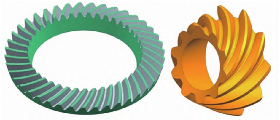
2.5 Hypoid Gear Pair Three-Dimensional Model
The design parameters and machine tool machining parameters of the hypoid gear pair are given in Tables 4 – 6. The tooth surface and transition surface vector equations of the large and small gears are solved to obtain the space point cloud coordinates of the tooth surfaces. To ensure the accuracy of the fitted tooth surfaces, the large and small gear tooth surfaces are discretized in the tooth length direction and tooth height direction, and the transition surfaces are discretized in the tooth height direction. Then, according to the geometric parameters of the large and small gears, the gear blank three-dimensional solid models are established, and the tooth surfaces obtained by fitting the point cloud spline surfaces are subtracted from hypoid gear blanks to obtain the three-dimensional model of hypoid gear pair.
| Parameter | Small Gear (Active, Left-Handed) | Large Gear (Right-Handed) |
|---|---|---|
| Number of Teeth | 10 | 41 |
| Module (mm) | 4.741 | |
| Shaft Angle (°) | 90 | |
| Offset Distance (mm) | -31.8 (Small Gear Down Offset) | |
| Tooth Surface Width (mm) | 33.637 | 28 |
| Outer Cone Distance (mm) | 117.178 | 101.26 |
| Helix Angle (°) | 49.9833 | 29.0000 |
| Pitch Cone Angle (°) | 15.5293 | 73.7000 |
| Root Cone Angle (°) | 14.1833 | 68.1333 |
| Pitch Cone Vertex Distance from Intersection Point (mm) | 18.11 | -3.05 |
| Face Cone Vertex Distance from Intersection Point (mm) | 11.80 | -3.60 |
| Root Cone Vertex Distance from Intersection Point (mm) | 21.52 | -1.36 |
| Parameter | Value |
|---|---|
| Cutter Head Nominal Diameter (inches) | 7.5 |
| Outer Cutter Tooth Profile Angle (°) | -24 |
| Inner Cutter Tooth Profile Angle (°) | 17 |
| Cutter Tip Offset Distance (inches) | 0.09 |
| Cutter Tip Fillet Radius (inches) | 0.04 |
| Machine Tool Installation Root Cone Angle (°) | 68.1333 |
| Horizontal Cutter Position (mm) | 41.11 |
| Vertical Cutter Position (mm) | 83.66 |
| Axial Wheel Position (mm) | -1.36 |
| Vertical Wheel Position (mm) | 0 |
| Parameter | Concave Surface (Outer Cutter) | Convex Surface (Inner Cutter) |
|---|---|---|
| Cutter Tooth Profile Angle | 14 | -31 |
| Cutter Tip Radius | 92.456 | 97.917 |
| Cutter Tip Fillet Radius (inches) | 0.0025 | 0.0025 |
| Machine Tool Installation Root Cone Angle (°) | -4.3 | -4.316667 |
| Radial Cutter Position (mm) | 89.8950 | 93.5458 |
| Angular Cutter Position (mm) | 87.1750 | 82.0249 |
| Axial Wheel Position (mm) | -2.33 | 2.60 |
| Vertical Wheel Position (mm) | 29.87 | 32.52 |
| Bed Position (mm) | 11.99 | 20.80 |
| Cutter Tilt Angle (°) | 21.2513 | 18.8262 |
| Cutter Rotation Angle (°) | 19.6319 | -34.2973 |
| Cutting Roll Ratio | 3.87250 | 4.03515 |
3. Hypoid Gear Pair Contact Analysis
3.1 No-Load Contact Analysis
The theoretical tooth surfaces of the large and small gears are established in their respective coordinate systems. To perform tooth contact analysis, a meshing coordinate system needs to be introduced. The meshing equations of the tooth surfaces are established, and the contact points and contact ellipses are calculated by iterative methods. The no-load contact impressions of the large and small gear tooth surfaces and the no-load transmission error of the hypoid gear pair are obtained.
3.1.1 Meshing Coordinate System and Equations
The meshing coordinate system is introduced. At a certain time during the meshing process, the radial vectors and unit normal vectors of the small and large gears in the meshing coordinate system are expressed. The instantaneous contact points of the tooth surfaces during meshing satisfy certain equations, which actually contain 5 independent equations. However, considering the relationships between the variables, there are 6 independent unknowns that cannot be directly solved. By giving a value to the small gear rotation angle as an input and solving iteratively, the contact points of the tooth surfaces can be obtained.
3.1.2 Contact Impressions and Transmission Error
The contact ellipses at the instantaneous meshing points are calculated according to the literature, and the no-load contact impressions of the large and small gear tooth surfaces are obtained. The no-load transmission error of the hypoid gear pair is calculated according to the actual rotation angles of the large and small gears and the definition of transmission error.
3.2 Loaded Contact LTCA Model
The three-dimensional solid models of the large and small gears are imported into Hypermesh software for meshing. A small gear full-tooth and large gear 18-tooth mesh model is established. The mesh model is then imported into ABAQUS finite element software for analysis. The material parameters, analysis type, and other parameters are set. The time-varying meshing characteristics under different load torques are analyzed, and the instantaneous contact area, equivalent meshing force, rotation angles of the large and small gears, and other parameters are extracted. The loaded transmission error, time-varying meshing stiffness, and actual tooth overlap are calculated according to the definitions.
The large and small gear models are meshed in Hypermesh software. Considering the calculation accuracy and efficiency, the large gear model is segmented to establish a suitable mesh model. The mesh model is then imported into ABAQUS with the set material and analysis parameters.
| Parameter | Value |
|---|---|
| Elastic Modulus (MPa) | 2.09e5 |
| Density (Kg·m – 3) | 7.85e3 |
| Poisson Ratio | 0.3 |
| Friction Coefficient | 0.1 |
| Contact Property | Hard Contact (“Hard” Contact) |
| Unit Type | C3D8R (Hexahedron One-Reduction Integral Unit) |
| Analysis Type | Implicit, Static Analysis |
| Main Analysis Step Length | 0.005 |
| Slip Type | Finite Sliding (Finite Slip) |
| Output Variables | CNORMF; CFNM; CMNM; CNAREA UR; COORD; CSTATUS; CFORCE; |
| Unit Number | Small Gear 124800; Large Gear 201600 |