
Abstract: This article focuses on the research of hypoid gear tooth side clearance design methods. It begins with an introduction to the importance of tooth side clearance in hypoid gear, followed by detailed discussions on theoretical design, manufacturing-based reverse design, and considerations of various factors such as load and thermal expansion. The aim is to determine a reasonable and scientific tooth side clearance value to ensure the proper functioning and performance of hypoid gear.
1. Introduction
Hypoid gear play a crucial role in many mechanical systems, especially in automotive applications. The proper design of tooth side clearance is essential for the smooth operation and longevity of these gears. In this section, we will discuss the background and significance of studying hypoid gear tooth side clearance.
1.1 Background of Hypoid Gear
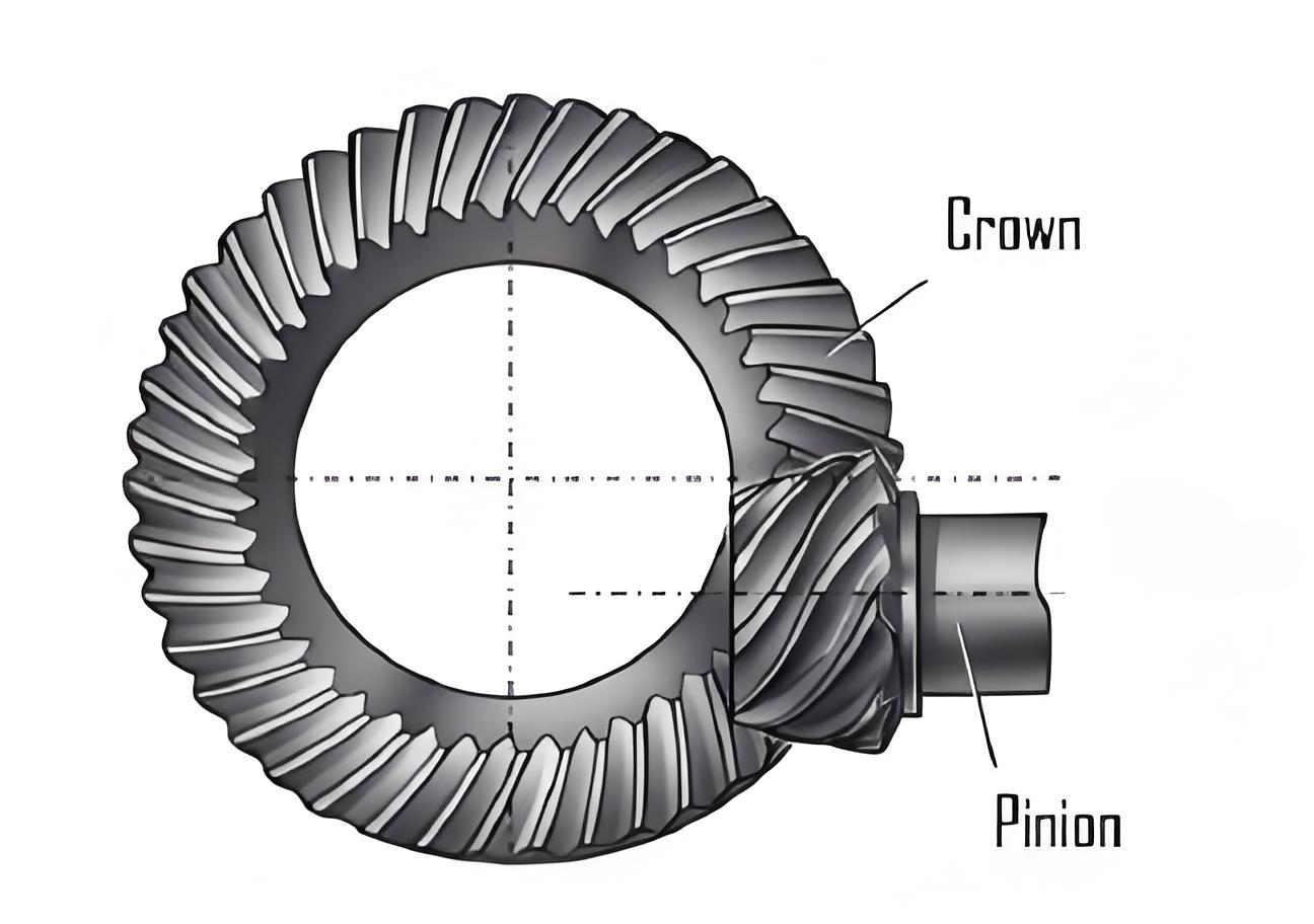
Hypoid gear is a type of bevel gear with a unique geometry that allows for non-intersecting and non-parallel shafts to transmit power. They are widely used in automotive differentials and other applications where high torque transmission and smooth operation are required.
1.2 Importance of Tooth Side Clearance
The tooth side clearance in hypoid gear serves several important purposes. Firstly, it allows for the formation of a lubricant film between the meshing tooth surfaces, which reduces friction and wear. Secondly, it provides room for hypoid gear to expand due to heat generated during operation, preventing gear seizure. However, if the tooth side clearance is too large, it can lead to meshing impact and increased noise, affecting the NVH (Noise, Vibration, and Harshness) performance of hypoid gear transmission.
2. Theoretical Design of Hypoid Gear Tooth Side Clearance
In this section, we will explore the theoretical aspects of designing the tooth side clearance of hypoid gear.
2.1 Gear Precision Standards
The gear precision standard used in this study is the national standard 7 – level precision. During the manufacturing process, hypoid gear precision is measured, and parameters such as indexing error and tooth form error are determined. Under a fixed gear installation center distance, the pitch error is an important factor affecting the variation of tooth side clearance.
2.2 Design Using Gleason Gear Calculation Software
By using the Gleason gear calculation software C – AGE for theoretical design, the design value of the meshing tooth side clearance for hypoid gear pair is obtained as 0.127 – 0.1778 mm. The relationship between pitch error and hypoid gear precision level is presented in Table 1.
| Precision Level | Active Gear Pitch Error (μm) | Driven Gear Pitch Error (μm) |
|---|---|---|
| 4 | 12 | 18 |
| 20 | 28 | |
| 32 | 45 | |
| 7 | 45 | 63 |
| 8 | 63 | 90 |
| 9 | 90 | 125 |
| 125 | 180 | |
| 10112 | 180 | 250 |
| 250 | 355 |
Based on the above analysis, a recommended gear tooth side clearance of 0.13 – 0.18 mm is obtained, which is in agreement with the design value.
2.3 Determination of Tolerance Values for 7 – Level Precision Gears
For 7 – level precision gears, the pitch error of the active gear is 45 μm, and that of the driven gear is 63 μm. The minimum and maximum side clearances for different pitch circle diameters are presented in Table 2.
| Pitch Circle Diameter (mm) | Minimum Side Clearance (mm) | Maximum Side Clearance (mm) | |
|---|---|---|---|
| 25.4 | 31.749746 | ||
| 31.75 | 38.09746 | 0.46 | 0.66 |
| 38.1 | 44.449746 | 0.41 | 0.56 |
| 44.45 | 50.79746 | 0.36 | 0.46 |
| 50.8 | 63.49746 | 0.30 | 0.41 |
| 63.5 | 76.19746 | 0.25 | 0.33 |
| 76.2 | 88.89746 | 0.20 | 0.28 |
| 88.9 | 101.59746 | 0.18 | 0.23 |
| 101.6 | 126.99746 | 0.15 | 0.20 |
| 127 | 152.39746 | 0.13 | 0.18 |
| 152.4 | 203.19746 | 0.10 | 0.15 |
| 203.2 | 253.99746 | 0.08 | 0.13 |
| 254 | 507.99746 | 0.05 | 0.10 |
| 508 | 1016 | 0.00 | 0.05 |
| 1041.4 | 2032 | 0.00 | 0.03 |
| 2057.4 | 3048 | 0.00 | 0.02 |
The cumulative tolerance value is 45 + 63 = 108 μm. When the other components of the 7 – level precision gear are at theoretical dimensions, the variation range of tooth side clearance calculated by the extreme value method is ±0.109 mm.
2.4 Determination of Theoretical Tooth Side Clearance Tolerance Values
The theoretical design standard tooth side clearance is 0.13 – 0.18 mm, with a mean value of 0.155 mm. Taking 0.155 mm as the median value for tooth side clearance adjustment, and considering the variation of 0.109 mm, the variation range of tooth side clearance is obtained as follows:
Upper limit: 0.155 + 0.109 = 0.264 mm
Lower limit: 0.155 – 0.109 = 0.044 mm
This means that when all components of the main reducer assembly are at theoretical dimensions, after adjusting the tooth side clearance according to 0.13 – 0.18 mm, the subsequent test variation range is 0.044 – 0.264 mm.
3. Reverse Design Based on Manufacturing Factors
In this section, we will consider the manufacturing process and its impact on the tooth side clearance of hypoid gears.
3.1 Gear Precision and Pitch Error
As mentioned earlier, the pitch error is related to the gear precision level. In the manufacturing process, each tooth may have manufacturing errors, which will affect the tooth side clearance. For example, in a product with a speed ratio of 4311, after analyzing the meshing relationship of the gears, it is found that after the driven gear rotates 11 circles, the measured first active gear can coincide with the meshing driven gear again. This shows that the meshing relationship is related to the gear speed ratio, and the measurement position of the tooth side clearance of the driven gear will change during the meshing movement.
3.2 Analysis of Reasons for Variation in Tooth Side Clearance during Measurement
The manufacturing errors of each tooth cause the variation in tooth side clearance measurement. The meshing relationship between gears is related to the gear speed ratio. When the gears are assembled in the main reducer assembly, the meshing movement of the active and driven gears causes the measurement position of the tooth side clearance of the driven gear to change.
3.3 Manufacturing Site Data Detection
For a certain type of main reducer assembly, the tooth side clearance before and after meshing detection was measured.
(1) During the main reducer assembly, the tooth side clearance of 50 sets of main reducer assemblies was measured, with 4 points measured in the circumferential direction for each set.
(2) After the main reducer assembly meshing detection, the tooth side clearance of the main reducer assembly was measured from the same identification position of the driven gear. The data variation range of the tooth side clearance is 0.10 – 0.21 mm, which has a certain difference from the theoretical calculation but is within the tolerance range calculated by the extreme value method.
3.4 Gear Expansion and Deformation during Operation
During operation, the gears are subjected to load and temperature changes, which cause expansion and deformation. According to the recommended separation coefficient of the main and driven gear meshing given by Gleason, it is 0.00635 mm. In a normal rear drive bridge operation, the operating temperature is about 70°C – 150°C. Based on empirical data, the deformation of steel at 100°C is 0.02 – 0.03 mm. Therefore, the expansion amount of the tooth surface during meshing is 0.01365 – 0.02365 mm. Considering the load and thermal expansion factors on the working surfaces of the active and driven gears and the thermal expansion factor on the non – working surfaces (considering the non – working surface expansion is mainly because of the gear heat deformation and the interference situation when the tooth tip enters the meshing), the deformation amount of the gear is calculated as follows:
Lower limit: (0.01365 + 0.02) × 2 = 0.0673 mm
Upper limit: (0.02365 + 0.03) × 2 = 0.1073 mm
This shows that when assembling this type of gear, the tooth side clearance value should not be less than 0.1073 mm. Otherwise, during the meshing process, there will be a risk of negative side clearance, which will cause tooth surface interference, 加剧 gear meshing surface impact, and lead to early failure and vibration noise.
3.5 Determination of Tooth Side Clearance for a Certain Type of Main Reducer Assembly
Combining the theoretical design value of tooth side clearance (0.127 – 0.1778 mm), the theoretical tolerance value based on the manufacturing process (0.044 – 0.264 mm), the measured assembly tooth side clearance value of the product (0.07 – 0.21 mm), and the deformation amount due to thermal expansion (not less than 0.1073 mm), a suitable tooth side clearance value for the main reducer assembly of this type of gear is determined to be 0.11 – 0.20 mm. This value can meet the assembly requirements, be compatible with the cumulative errors of other components in the main reducer assembly, avoid the risk of negative side clearance during gear meshing, and meet the manufacturing process requirements, avoiding resource waste caused by excessive precision.
3.6 Impact of Tooth Side Clearance on Gear Meshing Noise
The rear drive bridge transmits torque through hypoid gear, and the main source of noise is the noise generated during gear meshing. The main reason for gear meshing noise is the transmission error of the gears. Although theoretically, conjugate tooth surfaces without manufacturing errors should not produce transmission noise, in practice, due to the use of local conjugate contact methods in the manufacturing process, there will be a certain amount of mismatch, which allows for a certain amount of assembly error and adjustability during the assembly of hypoid gear pair. The tooth side clearance is an important part of hypoid gear mismatch amount. Therefore, during the operation of hypoid gear, the tooth side clearance will have an impact on hypoid gear meshing noise. If the tooth side clearance is too small or too large, it will lead to early failure and noise of the tooth surface.
4. Conclusions
In conclusion, the tooth side clearance parameter of hypoid gear during assembly into the main reducer assembly is related to multiple important control parameters such as gear precision, installation shaft, bearing and housing support stiffness, meshing mark, and design parameters. The research in this article aims to find an effective design and calculation method, clarify the theoretical and manufacturing process factors that affect the variation of tooth side clearance, accurately determine the important parameter value of tooth side clearance, avoid resource waste caused by excessive precision, meet the manufacturing process requirements, and satisfy the functional and performance requirements of hypoid gear. In future work and data collection, continuous improvement of the tooth side clearance defect rate should be carried out.