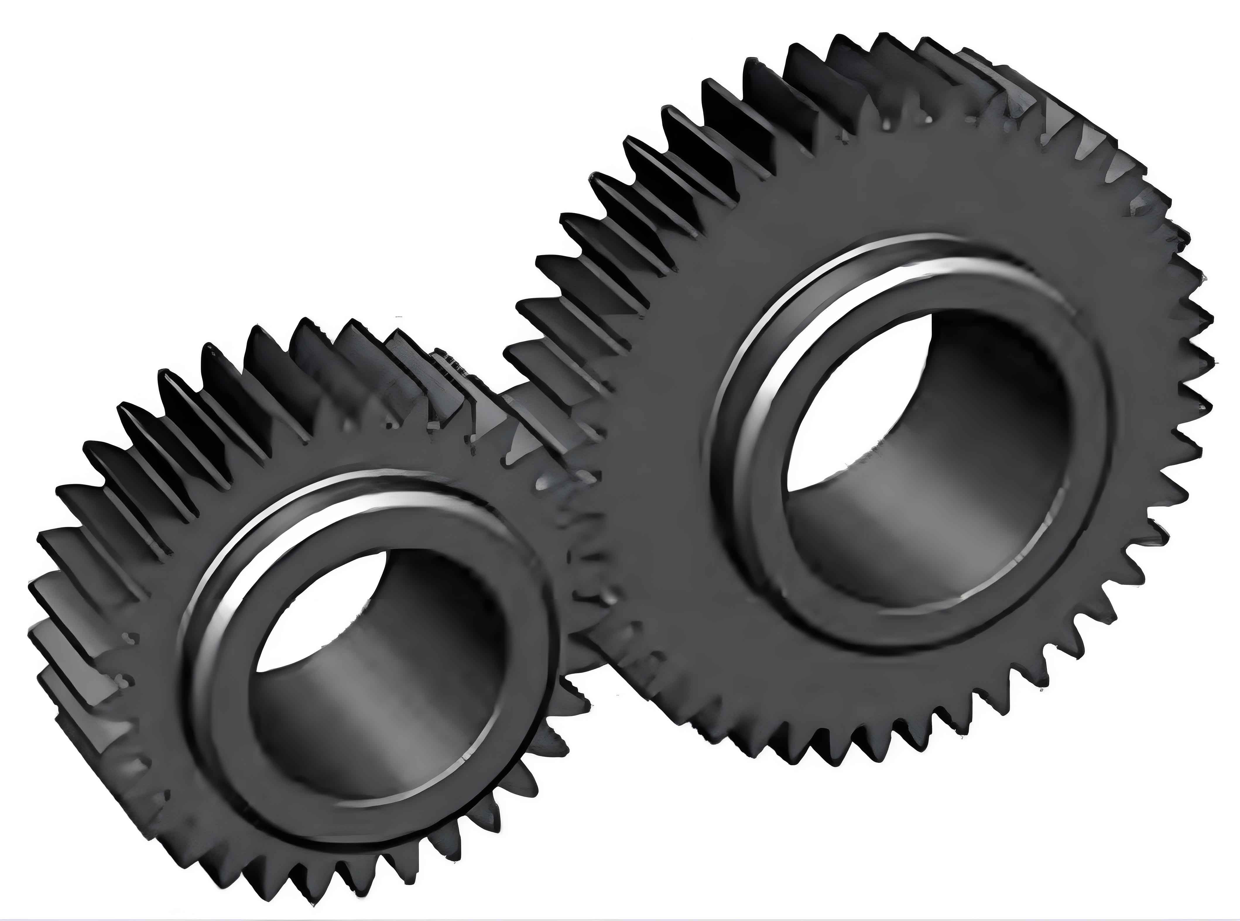
Abstract: This article focuses on the study of involute beveloid spur gear transmission error. Based on gear meshing principles and involute beveloid gear machining principles, relevant models are established and verified. The influences of different factors such as load, speed, and axis installation error on gear transmission error are analyzed in detail. The results provide valuable references for the design and application of involute beveloid spur gear.

1. Introduction
Spur gear transmission has many advantages such as good smoothness and constant transmission ratio. However, spur gear transmission error has a significant impact on various aspects of gear performance. Involute beveloid gears, with their unique characteristics, are widely used in some precision instruments. Previous studies on involute beveloid gears have mainly focused on tooth surface modification, machining, and dynamic characteristic analysis, while transmission error analysis has been relatively lacking. This article aims to fill this gap.
1.1 Research Background
Spur gear transmission is an important part of mechanical transmission systems. The accuracy of spur gear transmission directly affects the performance of the entire mechanical equipment. Involute beveloid gears have different characteristics from ordinary gears, and their transmission error analysis is of great significance for improving the performance of precision instruments.
1.2 Research Objectives and Significance
The main objective of this research is to establish a model for analyzing the transmission error of involute beveloid spur gear and to study the influence of various factors on the transmission error. The research results can provide theoretical support for the design and optimization of involute beveloid spur gear, and help to improve the transmission accuracy and performance of precision instruments.
2. Theoretical Basis of Involute Beveloid Spur Gear Transmission
2.1 Gear Meshing Principles
Gear meshing is based on the principle of conjugate tooth profiles. In the meshing process, the contact points of the two gears satisfy certain geometric relationships. The involute tooth profile has good meshing properties, which can ensure the smooth transmission of spur gear.
2.2 Involute Beveloid Gear Machining Principles
Involute beveloid gears are usually machined by special methods. The machining process needs to consider the characteristics of different cross-sections of spur gear and ensure that spur gear has the correct tooth profile and geometric dimensions.
3. Modeling of Involute Beveloid Spur Gear Transmission
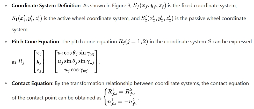
3.1 Establishment of the Cone Model Based on the Pitch Cone

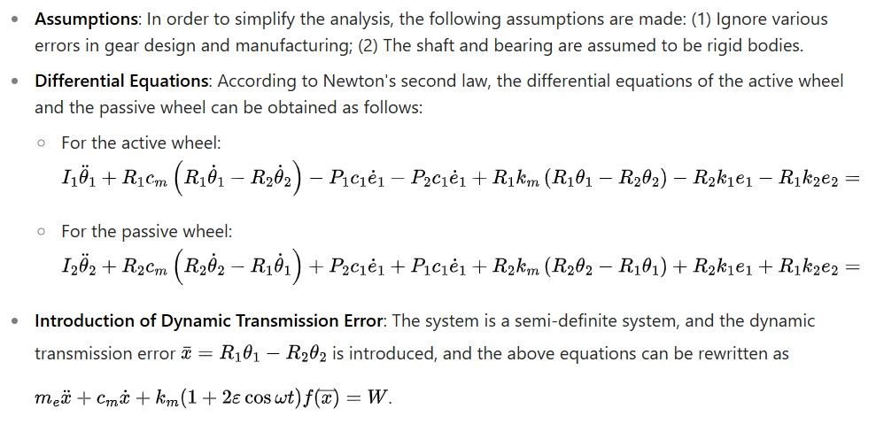
3.2 Establishment of Spur Gear Dynamics Analysis Model

3.3 Establishment of Spur Gear Transmission Error Equation

4. Modeling and Verification of Involute Beveloid Gear
4.1 Three-Dimensional Modeling of Involute Beveloid Gear
- Tooth Surface Mathematical Model: According to the mathematical model based on the pitch cone in Section 3.1, the accurate tooth surface equation can be obtained, and then the digital three-dimensional modeling can be completed.
- Modeling Process in UG: The three-dimensional coordinates of the points on the tooth surface are imported into UG11.0, and according to the point-line-surface modeling principle, the contour lines of the tooth surface are obtained, the tooth profile surface is fitted, and the single tooth feature of spur gear is constructed. Then, by extracting geometric features, bounded planes, stitching, removing parameters, and arraying, a more accurate three-dimensional model can be generated.
4.2 Verification of spur Gear Model
- Digital Rolling Inspection Test: Spur gear model established with the above parameters is assembled in UG software and then a digital rolling inspection test is carried out. The contact area of spur gear teeth is observed to be a line contact, which verifies the theoretical correctness of the tooth surface equation and the modeling method.
- ADAMS Simulation Verification: The established involute beveloid spur gear model is imported into ADAMS, and boundary conditions and parameters are set for simulation. By comparing the theoretical and actual transmission ratios, it is verified that spur gear model is correct.
5. Analysis of Transmission Error of Involute Beveloid Spur Gear under Different Working Conditions
5.1 Influence of Load on Transmission Error
- Simulation Setup: Different loads of 50, 100, 150, 200, and 250 N·m are applied to the passive wheel, with a constant speed of 360 r/min, a simulation time of 1 s, and 5000 simulation steps.
- Results and Analysis: As the load increases, the maximum transmission error, minimum transmission error, and root mean square of the transmission error all increase. However, when the load reaches a certain value, the transmission error tends to be stable. The transmission error fluctuates periodically near 0.
5.2 Influence of Speed on Transmission Error
- Simulation Setup: Different constant speeds of 400, 500, 600, 700, and 800 r/min are applied to the active wheel, with a constant load of 200 N·m, a simulation time of 1 s, and 5000 simulation steps.
- Results and Analysis: As the speed increases, the average transmission error still fluctuates near 0, but the error center line shifts away from 0, and irregular fluctuations occur at 800 r/min. The maximum, minimum, and root mean square of the transmission error increase approximately linearly with the increase of speed.
5.3 Influence of Axis Installation Error on Transmission Error
- Simulation Setup: Different axis position errors of 0, 0.3, 0.6, 0.9, 1.2, and 1.5 mm are given to the passive wheel axis, with a constant speed of 600 r/min and a constant load of 200 N·m, while keeping other parameters unchanged.
- Results and Analysis: As the axis installation error increases, the average transmission error, maximum transmission error, minimum transmission error, and root mean square of the transmission error first decrease, then increase, and then decrease again, showing an “M” shape as a whole.
6. Conclusions
- The parallel-axis involute beveloid spur gear has high transmission accuracy without axis installation error, and the transmission error fluctuates periodically near 0, which is suitable for high-precision transmission instruments.
- As the load increases, the transmission error of the involute beveloid spur gear increases, but it tends to be stable within a certain range.
- As the speed increases, the average transmission error of the involute beveloid spur gear first decreases and then increases, but still fluctuates near 0. The minimum transmission error, maximum transmission error, and root mean square of the transmission error increase approximately linearly with the increase of speed, indicating that the transmission error of the involute beveloid spur gear is sensitive to speed changes.
- As the axis installation error increases, the average transmission error, maximum transmission error, minimum transmission error, and root mean square of the transmission error first decrease, then increase, and then decrease again, showing an “M” shape as a whole. This shows that although the axis error may occur due to the increase of the center distance after long-term work of the involute beveloid spur gear, it actually improves its transmission accuracy to some extent.
In summary, this research provides a comprehensive analysis of the transmission error of involute beveloid spur gear, which is of great significance for the design and application of such spur gear. Future research can further explore the optimization of spur gear design and manufacturing processes to further improve the performance of involute beveloid spur gear.
