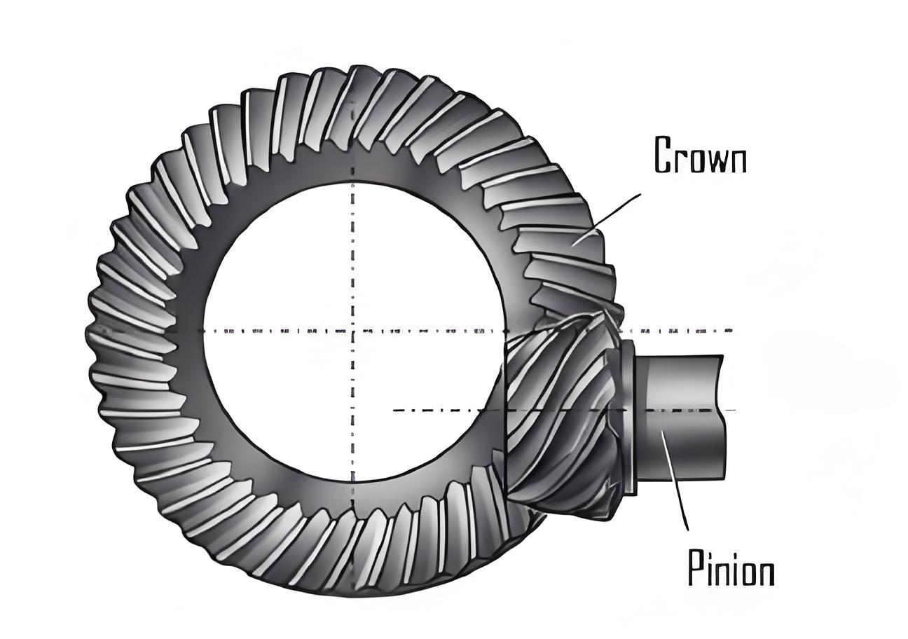
1. Hypoid Gear Finite Element Modeling
1.1 Mesh Division
| Software | Unit | Jacobian Coefficient |
|---|
| HyperMesh | – | >0.7 |
1.2 Material Property Definition
| Software | Analysis Step |
|---|
| ABAQUS | Dynamic, Implicit |
1.3 Tooth Surface Contact Settings
| Contact Pair | Discrete Method | Tangential Behavior | Normal Behavior |
|---|
| Small gear concave surface – Large gear convex surface | surface to surface | – | – |
2. Tooth Surface Contact Spots
2.1 Forward Meshing
| Meshing Direction | Contact Surface | Contact Area Shape | Contact Area Change | Meshing In and Out |
|---|
| Forward | Small gear concave surface – Large gear convex surface | Oval | Increase first and then decrease | Large end in, small end out |
2.2 Reverse Meshing
| Meshing Direction | Contact Surface | Contact Area Shape | Meshing In and Out | Movement of Meshing Position |
|---|
| Reverse | Small gear convex surface – Large gear concave surface | Oval | Small end in, large end out | Large gear: from tooth top to tooth root; Small gear: from tooth root to tooth top |
3. Tooth Root Bending Stress
3.1 Stress Cloud Diagram
| Gear | Main Stress at Tooth Root | Stress at Tooth Surface Contact Position |
|---|
| Small gear | Tensile stress | Compressive stress |
| Large gear | Tensile stress | Compressive stress |
3.2 Stress Change Curve
| Gear | Stress Change of Danger Point |
|---|
| Small gear | Tensile stress first, then compressive stress |
| Large gear | Compressive stress first, then tensile stress |
4. Gear Contact Ratio
4.1 Contact Ratio Definition
ε = ΔT/Δt
4.2 Contact Ratio Change with Load
| Load (Nm) | Contact Ratio |
|---|
| Near 0 | 1 |
| Increase | Gradually increase (up to about 2.5) |
5. Gear Transmission Error
5.1 Transmission Error Definition
TE = (φ2-φ2^(0))-Z1/Z2(φ1-φ1^(0))
5.2 Transmission Error Simulation Results
| Load (Nm) | Transmission Error Curve Shape | Peak of Transmission Error | Change of Transmission Error Amplitude |
|---|
| 10 | Parabolic | Appears once per tooth rotation of small gear | Decrease with load increase |
| <400 | – | Same angular displacement corresponding to peak | Decrease with load increase |
| >400 | – | – | First decrease to minimum, then increase to maximum, finally stabilize |
5.3 Transmission Error Test
| Test Item | Result |
|---|
| Influence of Lubricating Oil Temperature | Almost no influence |
| Comparison with Simulation Results | Consistent in amplitude and change trend |
6. Conclusion
| Meshing Characteristic | Conclusion |
|---|
| Tooth surface contact area | Oval, increase first and then decrease during meshing |
| Tooth root bending stress | Danger points of both gears mainly bear tensile stress, with different stress change sequences for small and large gears |
| Contact ratio | Increase with load, with decreasing growth rate |
| Transmission error | Not affected by temperature, greatly affected by load, with specific amplitude change trend |
