
Abstract
High reduction hypoid gear has the advantages of high transmission efficiency, strong carrying capacity and good silence. It is suitable for precision, high speed and heavy duty transmission systems. This paper proposes a point contact HRH tooth surface design method based on the conventional machining method of spiral bevel gear, and completes the motion simulation, finite element analysis and test verification of the gear. The research contents include the topological design method of point contact tooth surface, the meshing motion simulation, the finite element load contact simulation and the dynamic performance test. The results show that the tooth surface contact spot rolling is in good agreement with the design simulation, and the trend of high reduction hypoid gear amplitude-frequency characteristic testing is consistent with that of simulation.
1. Introduction
1.1 Research Background and Significance
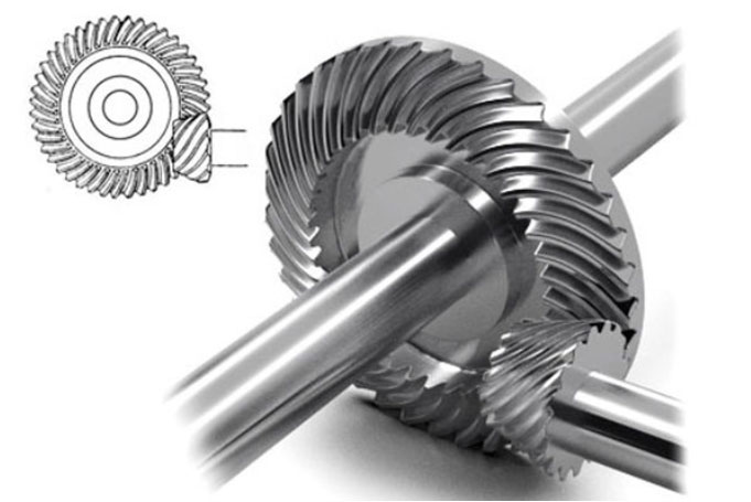
High reduction hypoid gear can achieve a large transmission ratio with fewer teeth and is suitable for high-speed, high-load and high-precision transmission systems. However, its tooth surface design and performance control are difficult due to the complex space meshing theory and surface topology structure. The research on the dynamic meshing performance of high reduction hypoid gear is of great significance for the integration, lightweight and high power density transmission of electromechanical transmission device.
1.2 Research Status at Home and Abroad
1.2.1 Research Status of High Reduction Ratio Gear Transmission Devices
Many scholars have studied worm gears and planetary gears. For example, Li Zhe realized the parametric modeling of the worm gear with high accuracy and analyzed the contact status of the tooth surface. Peng Donglin proposed an adaptive transformation method for the instrument and its application object. Liu Jing established the dynamic model of the planetary gear reducer. However, these gears have some disadvantages such as low transmission efficiency, high manufacturing cost and difficult maintenance.
1.2.2 Research Status of Spiral Bevel Gears
Spiral bevel gears have high transmission efficiency and low noise level, and are widely used in various fields. Scholars have studied the processing methods, dynamic performance and tooth surface modification of spiral bevel gears. For example, Zhang Yu proposed a tooth surface mismatch design method for the large wheel of the spiral bevel gear. Li Fei studied the influence of different factors on the dynamic performance of the spiral bevel gear. Wei Bingyang established the bending fatigue life simulation model of the spiral bevel gear.
1.2.3 Research Status of Gear Dynamic Meshing Performance
The dynamic meshing performance of high reduction hypoid gear directly affects the reliability and life of high reduction hypoid gear transmission. Scholars have studied the influence of factors such as tooth surface wear, thermal deformation and uncertainty on the dynamic meshing performance of high reduction hypoid gear. For example, Shen Zhixian established the Archard wear model of high reduction hypoid gear and analyzed the influence of tooth surface wear on the meshing stiffness. Zhang Xin established the finite element analysis model of high reduction hypoid gear system and analyzed the influence of deformation on the contact displacement. Ren Zhaohui established the dynamic model of the helical gear and analyzed the influence of various factors on the vibration performance of the system.
1.3 Research Contents of This Paper
This paper proposes a point contact tooth surface topological design method based on the meshing principle of hypoid gear transmission. The specific research contents are as follows:
- Analyze the geometric parameter design constraints of high reduction hypoid gear, and establish the tooth surface equations of the large and small wheels.
- Optimize the processing parameters of the small wheel, establish the 3D model of the gear, and complete the motion simulation of the gear.
- Use ADAMS software to simulate the meshing motion of high reduction hypoid gear and analyze the vibration characteristics of the gear. Establish the 3D finite element analysis model of the gear and analyze the stress distribution of the tooth surface.
- Conduct the rolling inspection test, dynamic performance test and transmission efficiency test of high reduction hypoid gear to verify the correctness of the gear design method and simulation process.
2. Establishment of Mathematical Model of High Reduction Hypoid Gear Tooth Surface
2.1 Design of Contour Forming Method
2.1.1 Pitch Cone Design of Hypoid Gear
The pitch cone of the hypoid gear is designed to ensure that the large and small wheels are tangent at the node. The meshing relationship satisfies the equation:
The key to the design is to solve the problems of tooth shrinkage and the matching of the tangent pitch cones of the large and small wheels.
2.1.2 Principle of Node Longitudinal Displacement
The tooth height shrinkage depends on the sum of the dedendum angles of the large and small wheels. The longitudinal displacement coefficient is introduced at the node to change the pitch cone angle and the position of the two pitch cones tangent, making the geometric design of the high reduction hypoid gear more flexible.
2.1.3 Design Pitch Cone and Cutting Pitch Cone
The cutting pitch cone and the design pitch cone of the bevel gear are different. The actual tooth surface and the theoretical tooth surface are inconsistent, which requires the correction of the tooth surface to ensure the correct meshing of the large and small wheels.
2.2 Calculation of Gear Geometric Parameters
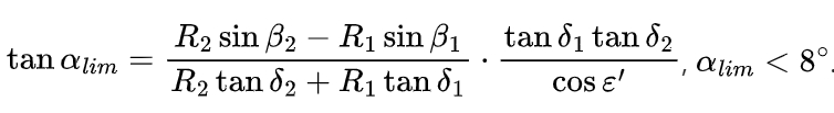
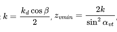
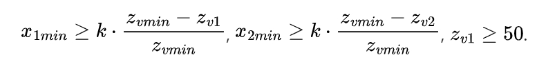
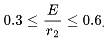
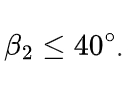
The geometric parameter design of HRH gear needs to consider the cutting conditions, meshing conditions and loading strength balance conditions. The specific calculation formulas and constraints are as follows:
1.Limit pressure angle:
2.Limit curvature radius:

3.Large wheel pitch cone angle:
4.Number of teeth and radial displacement coefficient:
5.Small wheel offset distance:
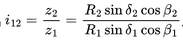
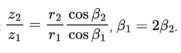
6.Large wheel spiral angle:
7.Reduction ratio and spiral angle relationship:
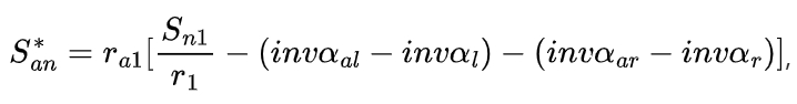
8.Small wheel addendum width:
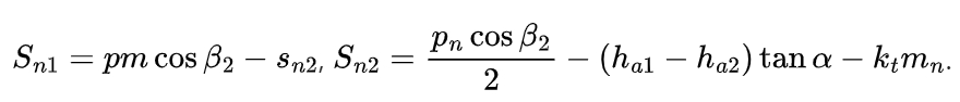
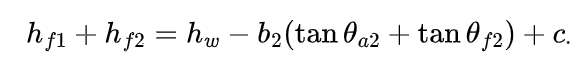
9.Minimum slot width:

10.Large wheel node radius:
11.Large wheel pitch cone angle approximation:
2.3 Establishment of Large Wheel Tooth Surface Equation
2.3.1 Brief Description of Processing Method
The processing of spiral bevel gears is based on the principle of “imaginary generating gear”. The commonly used processing methods include forming method and generating method (hobbing method). The HFT method and HGM method are the common processing method combinations of hypoid gear.
2.3.2 Modification of Large Wheel Cutter Profile
The large wheel of the designed 3:60 gear is processed by the forming method, and the cutter profile curvature is compensated by the quadratic parabola modification of the large wheel cutter along the w direction. The cutter surface equation and the modified cutter profile equation are given.
2.3.3 Modification of Longitudinal Curvature
The longitudinal curvature is corrected by establishing a coordinate system. The cutter equations and the merged equations are given, and the relationship between the radius and curvature of the cutter tip is also given.
2.3.4 Derivation of Large Wheel Tooth Surface Equation
The large wheel tooth surface equation is derived by coordinate transformation. The conversion matrices and the large wheel tooth surface equation and normal vector are given.
2.4 Derivation of Conjugate Pinion Tooth Surface Equation
The conjugate pinion tooth surface equation is derived based on the conjugate surface principle. The transformation matrices and the pinion tooth surface equation are given, and the meshing equation is also established.
3. Topological Design of Point Contact HRH Tooth Surface
3.1 Processing Parameters of Large Wheel
The large wheel of high reduction hypoid gear is processed by the forming method, and the processing parameters include cutter parameters and machine tool adjustment parameters. The cutter pressure angle difference is compensated by rotating the cutter head, and the changed cutter position parameters are calculated.
3.2 Optimization and Solution of Pinion Processing Parameters
3.2.1 Second-Order Osculating Surface
The second-order osculating surface is defined, and its differential geometric properties are analyzed. The surface equation and the relationship between the osculating surface and the original surface are given.
3.2.2 Topology of Tooth Contact Area
The topology of the tooth contact area is analyzed, and the contact ellipse, contact path, transmission error and other parameters are calculated. The equations for calculating these parameters are given.
3.2.3 Solution of Pinion Processing Parameters
The pinion processing parameters are solved by the surface synthesis method. The nonlinear equations are established and solved by Matlab, and the processing parameters of the 3:60 high reduction hypoid gear are given.
3.2.4 Tooth Surface Contact Performance
The tooth surface normal modification amount is calculated, and the ease-off surface is constructed. The contact ellipse, contact path and transmission error are analyzed, and the results show that high reduction hypoid gear has good meshing performance.
3.3 Digital Modeling of Tooth Surface
3.3.1 Solution of Tooth Surface Mesh
The tooth surface grid is divided by the rotation projection principle, and the coordinates of the grid points are calculated. The equations for calculating the coordinates of the four endpoints and the grid points on the boundaries are given, and the 3D model of high reduction hypoid gear is established.
3.3.2 3D Meshing Simulation
The 3D meshing simulation of high reduction hypoid gear is carried out, and the contact state of the tooth surface is observed. The simulation results show that the gear has good meshing performance and the contact area is reasonable.
4. Motion Simulation and Finite Element Contact Analysis of High Reduction Hypoid Gear
4.1 Kinematic Simulation Analysis of High Reduction Hypoid Gear
4.1.1 Establishment of Gear Kinematic Model
The high reduction hypoid gear kinematic model is established by ADAMS software. The settings of the model include unit, component information, connection, contact parameters, drive and load. The contact force is calculated by the Impact function, and the parameters of the function are given.
4.1.2 Analysis of Motion Simulation Results
The motion simulation results are analyzed, and the angular acceleration amplitude of the large wheel is obtained. The simulation results show that the high reduction hypoid gear has good meshing performance and the vibration is stable under different working conditions.
4.2 Finite Element Contact Analysis of High Reduction Hypoid Gear
4.2.1 Finite Element Analysis Process of High Reduction Hypoid Gear
The finite element analysis model of high reduction hypoid gear is established by ABAQUS software. The analysis steps include preprocessing, assigning material mechanical properties, meshing, setting analysis steps and interactions, and outputting variables. The tetrahedral mesh is used for meshing, and the mesh parameters are given.
4.2.2 Analysis of Finite Element Simulation Results
The finite element simulation results are analyzed, and the contact stress and bending stress of the tooth surface are obtained. The results show that the contact area is reasonable, the stress distribution is uniform, and high reduction hypoid gear has high strength and good meshing performance. The contact stress and bending stress curves under different loads are given, and the variation trends of the stresses are analyzed.
5. Dynamic Performance and Transmission Efficiency Test of High Reduction Hypoid Gear
5.1 Rolling Inspection of HRH Tooth Surface Contact Spot
The tooth surface contact spots of the 3:60 high reduction hypoid gear are obtained by the rolling inspection test. The contact spots are elliptical and located in the middle of the large wheel meshing surface, close to the small end. The actual contact spots are consistent with the simulation results, which verifies the feasibility of the gear point contact design method.
5.2 Test Bench Setup
A closed gearbox is designed for the 3:60 high reduction hypoid gear, and the test bench is built. The test bench consists of a motor, torque sensors, a magnetic powder brake, and a loading controller. The vibration signals of high reduction hypoid gear are collected by the M + P data acquisition device. The sensor probes are pasted on the vertical, axial, and horizontal positions of the output gear meshing.
5.3 Dynamic Performance Test
5.3.1 Vibration Testing
The dynamic performance test of the gearbox is carried out under different working conditions. The motor speed is set to 710r/min, 1410r/min, and 2100r/min, and the load is set to 50N/m and 200N/m. The vibration acceleration amplitude of high reduction hypoid gear is measured, and the sampling data is set according to the maximum speed of 2100r/min.
5.3.2 Vibration Data Analysis
The vibration data is analyzed, and the vibration acceleration amplitude of high reduction hypoid gear is obtained. The results show that the vibration acceleration amplitude of high reduction hypoid gear increases with the increase of the speed and decreases with the increase of the load. The vibration characteristics of high reduction hypoid gear are analyzed, and the influence of the shaft frequency on the meshing frequency is discussed.
5.4 Transmission Efficiency Test
5.4.1 Transmission Efficiency Testing
The transmission efficiency test of the high reduction hypoid gear is carried out using the test bench. The input and output torque of high reduction hypoid gearbox are measured, and the transmission efficiency is calculated. The test conditions include three speeds of 1500r/min, 1800r/min, and 2400r/min, and the load range of the large wheel is 83 – 295Nm.
5.4.2 Test Result Analysis
The test results are analyzed, and the transmission efficiency curve of high reduction hypoid gear is obtained. The results show that the transmission efficiency of high reduction hypoid gear increases with the increase of the speed and decreases with the increase of the load. The factors affecting the transmission efficiency are discussed, and the measures to improve the transmission efficiency are proposed.
6. Conclusions and Prospects
6.1 Conclusions
- A point contact tooth surface design method for high reduction hypoid gear is proposed, and the geometric model and tooth surface equations of high reduction hypoid gear are established.
- The processing parameters of high reduction hypoid gear are optimized, and the 3D model and motion simulation of high reduction hypoid gear are completed. The simulation results show that the gear has good meshing performance.
- The finite element analysis of high reduction hypoid gear is carried out, and the contact stress and bending stress of the tooth surface are obtained. The results show that the stress distribution is reasonable and high reduction hypoid gear has high strength.
- The dynamic performance and transmission efficiency tests of high reduction hypoid gear are completed, and the test results are consistent with the simulation results, which verifies the correctness of high reduction hypoid gear design method and simulation process.
6.2 Prospects
- The kinematic analysis and transmission efficiency calculation of high reduction hypoid gear need to be further studied, considering the influence of lubrication, friction and other factors.
- The establishment of the transition surface of the pinion is an important research direction, which can improve the accuracy of the simulation and the strength of high reduction hypoid gear.
- A more efficient meshing method for high reduction hypoid gear needs to be explored to reduce the calculation amount and improve the simulation accuracy.
- The vibration test of high reduction hypoid gear should be further improved, including the detection of the oil temperature and noise of the gearbox, and the selection of more load and speed conditions. The design method of the gearbox should also be described in more detail.