
Abstract
Rolling forming technology can effectively improve the utilization rate of metal materials and improve the fatigue strength of gears. The rolling forming process of straight cylindrical gear was simulated by using DEFORM software, and the changes of equal stress field, equivalent strain field and rolling force were analyzed. The formation mechanism of lug defects in rolling was explored, and the action law of friction coefficient on lug was studied, the optimization of friction coefficient oriented to lug control was realized, which could provide a theory for the rolling forming of straight cylindrical gear.
0. Introduction
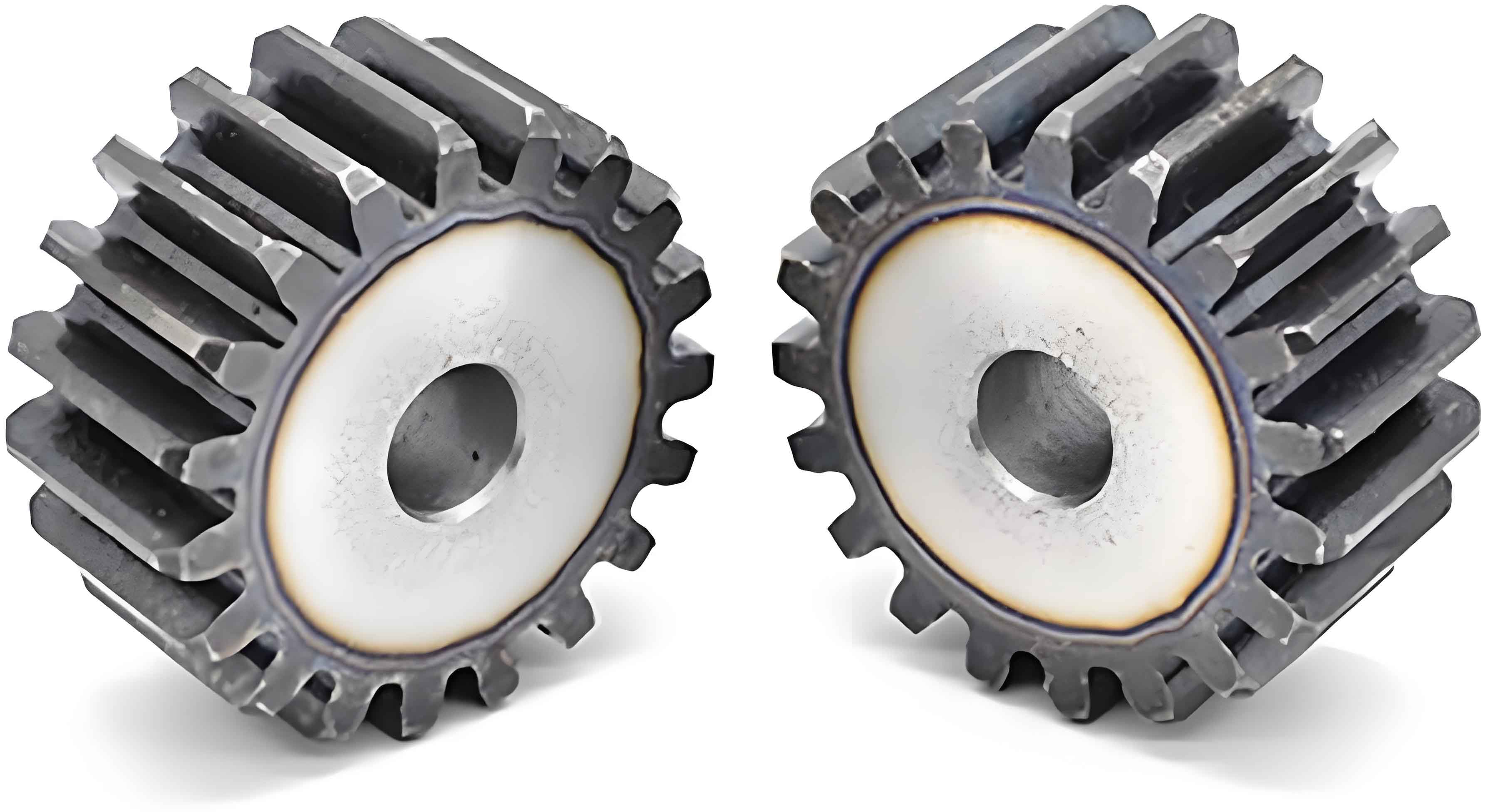
Straight cylindrical gear is a key component for transmitting motion and power. Traditional machining processes such as hobbing, shaping, milling, and turning cut the metal flow lines, which severely weakens the fatigue strength of the gear. Gear rolling near-net-shape forming technology is a plastic forming manufacturing process. During the rolling process, the tooth profile is formed by the forced meshing of the die wheel and the gear blank. The complete metal flow lines can effectively increase the fatigue strength of the gear and extend its service life.
Many scholars at home and abroad have studied the rolling forming technology of cylindrical gears. WEI et al. numerically simulated the deformation, heat generation, and microstructure evolution of a cross wedge rolling part using finite element software, taking an automobile oil pump shaft made of 42CrMo material as the research object. YUAN et al. studied the effects of the unidirectional and reciprocating rotations of the T2 worm on the hardness, strain distribution, and flow line distribution of the worm tooth surface through numerical simulation and experiments. ZHANG et al. established an equivalent model of a continuous helical groove hydrostatic lead screw and obtained the axial motion error of the nut by combining the bisection method and the finite difference method. DUDZIAK et al. analyzed the geometries of the internal and external teeth of an involute spline gear ring and introduced the general manufacturing process of the gear ring and the measurement results of the tooth profile deviation. NISTOR et al. studied the deformation mechanism of the spur gear and the influence of the gear geometric parameters from the perspectives of tooth forming and load evolution, and obtained a spur cylindrical gear with good quality through experiments. The maximum pressing force simulation value was basically consistent with the experimental value. SIECZKAREK et al. studied three influencing factors, namely friction, blank cutting process and edge performance, and process strategy optimization, in order to improve the defect of insufficient filling of the first tooth in the incremental forming process. BRECHER et al. studied the rolling process parameters of different specifications of gears by using the finite element numerical simulation method and reduction analysis. SABKHI et al. constructed a model of the cutting force in the rolling forming process. FU Xiaobin revealed the influence of the process parameters on the internal microstructure of the metal in the rolling of large modulus gears by studying the changes in the microstructure during the near-net-shape forming process. ZHU Xiaoxing et al. studied the hot rolling of large modulus gears, established a microstructure evolution model, and analyzed the variation law of the rolling force during the rolling process. QIAO Shuo et al. studied the flow law of the metal material in the rolling process using DEFORM – 3D. LIU Huimin gave the determination principle of the structural parameters of the cylindrical gear die wheel blank, proposed a tooth profile modification scheme to improve the rolling forming quality, and carried out simulation verification. ZHAO Bing studied the forming mechanism of the axial rolling of the spur cylindrical gear and analyzed the electromagnetic induction heating principle and the forming mechanism of the gear axial rolling process in detail. MA Ziyong et al. proposed a new process of forced indexing axial rolling forming and studied the gear generation principle, free indexing error, material flow mechanism, workpiece tooth height growth, roll design method, experimental machine tool development, and rolled part accuracy. ZHANG Yuming studied the rolling life of the die wheel, analyzed the main process, mechanism, quantitative calculation of fatigue life, and crack propagation analysis method of fatigue failure. WANG Yu studied the material flow law in the process of axial rolling gear and analyzed the stress situation of the gear blank during the forming process. ZHANG Shaolin carried out the numerical simulation of the rolling forming of the bevel gear, analyzed the formation process of the protrusions on the left and right sides of the tooth profile in the bevel gear rolling process, and studied the formation mechanism of the lug defect.
The above research results provide a good research foundation for the application of the gear rolling near-net-shape forming technology. Based on this, the authors of this paper use the DEFORM finite element software to numerically simulate the hot rolling forming process of the spur cylindrical gear, analyze the variation laws of the equivalent stress field, equivalent strain field, and rolling force in the X, Y, and Z directions during the hot rolling process, study the formation mechanism and suppression method of the lug defect in the rolling process, and provide technical support for the industrial application of the spur cylindrical gear rolling near-net-shape forming technology.
1. Establishment of Gear Rolling Equivalent Model
1.1 Derivation of Tooth Surface Equation
The end face coordinate system of the involute spur cylindrical gear. The XαOαYα plane is the normal section of the involute surface, and its profile is a standard involute. In the X2O2Y2 coordinate plane, I1 and I2 are two involutes of the cylindrical gear that are symmetrical about the X-axis, and θ0 is the initial angle of the involute. Assuming that the base circle radius of the involute gear is rb, and the tangent point of the normal of an arbitrary point M on the involute and the base circle is N, taking θ as the parameter, according to the properties of the involute, MN=rbθs. The tooth surface equation of the standard involute cylindrical gear can be derived as follows:
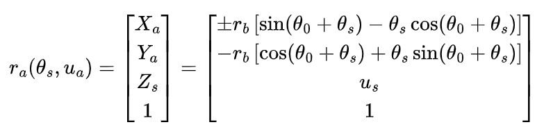
where uα is the axial position coordinate parameter of the cylindrical gear tooth surface; ± represents the left and right involutes, respectively.
1.2 Construction of Rolling Model
The rolling process of the gear is mainly divided into three stages: the preliminary indexing stage, the tooth profile forming stage, and the tooth profile finishing stage.
1.2.1 Preliminary Indexing Stage
In the preliminary indexing stage, a certain tooth profile is initially extruded on the gear blank by the die wheel.
1.2.2 Tooth Profile Forming Stage
In the forming stage, it is necessary to ensure that the die wheel can stably feed and bite in while improving the processing efficiency, so that the outer metal of the gear blank can plastically flow to form the target tooth profile.
1.2.3 Tooth Profile Finishing Stage
In the finishing stage, the die wheel no longer performs radial feed movement, but alternately rotates forward and backward to complete the tooth profile finishing process, thereby obtaining a higher quality target tooth profile and reducing or even eliminating the subsequent cutting amount.
Based on the tooth surface equation derived in Section 1.1, by substituting different parameter groups, the coordinates of each point on the tooth surface can be obtained. To facilitate obtaining the coordinates of points on the gear tooth surface under different parameter conditions, MATLAB programming is used in this paper to solve the tooth profile coordinates of the die wheel. The basic parameters of the die wheel and the target gear are shown in Table 1.
| Parameter | Target Gear | Die Wheel |
|---|---|---|
| Module / mm | 2 | 2 |
| Pressure Angle / (°) | 20 | 20 |
| Number of Teeth | 19 | 53 |
| Addendum Coefficient | 1 | 1 |
| Clearance Coefficient | 0.25 | 0.25 |
Substituting the data in Table 1 into the written die wheel tooth profile program, the die wheel tooth profile points are solved. Import it into UG software to fit the surface, complete the construction of the three-dimensional model, and then assemble it to obtain the rolling process model.
Based on the established model and the measurement volume function of UG software, the tooth volume of the straight spur gear is obtained, and the relevant dimensions of the gear blank are obtained by the equal volume method. Since hot rolling is a plastic forming process, theoretically, the volume of the gear blank remains unchanged before and after extrusion, the area . Assuming that the axial dimension of the gear blank remains unchanged, the initial diameter of the gear blank can be calculated according to the principle that the cross-sectional area of the blank remains unchanged before and after deformation.
2. Establishment and Parameter Setting of Simulation Model
2.1 Establishment of Numerical Simulation Model
In this paper, the numerical simulation model is simplified and assumed as follows: the die wheel is assumed to be a rigid body, ignoring the elastic deformation of the die wheel; the gear blank is a homogeneous material and a rigid-plastic body; the contact friction coefficient between the gear blank and the die wheel is a constant; and the ambient temperature during the rolling process remains unchanged. To reduce the computational load of the simulation, considering that the metal inside the gear blank basically does not undergo plastic deformation, a hole is drilled in the center of the gear blank to realize the motion setting. To improve the efficiency of the simulation analysis and reduce the simulation time, half of the gear blank is taken as the object of the simulation analysis. Finally, the modified three-dimensional model is imported into the DEFORM software to build the numerical simulation model.
2.2 Parameter Setting of Simulation
Based on the above ideas, the parameters of the die wheel and the gear blank are set as shown in Table 2.
| Parameter | Value | Parameter | Value |
|---|---|---|---|
| Gear Blank Temperature / °C | 950 | Initial Bite Depth / mm | 0.3 |
| Die Wheel Temperature / °C | 20 | Friction Coefficient | 0.3 |
The total number of meshes is set to 101536, and the metal part of the gear blank with a thickness of 4 mm inward from the outer circle of the gear blank, which is the main deformation part, is locally refined with a refinement ratio of 0.01.
The middle section plane of the gear blank, that is, the symmetry plane, is set as the symmetry constraint. To prevent the gear blank from slipping during the rolling process, the velocities in the X, Y, and Z directions of the inner ring surface of the gear blank are set to 0, and the velocity in the Y direction of the front and rear surfaces is set to 0, forming a closed state of the gear blank. Based on the actual working conditions, the radial feed speed of die wheel 1 is set to 0.1 mm/s, the rotation speed is set to 2.2525 rad/s, and the rotation speed around the center of the gear blank, that is, the Y-axis, is set to 6.2832 rad/s. The settings of die wheel 2 are the same as those of die wheel 1, except that the radial feed direction of the die wheel is reversed.
3. Numerical Simulation Analysis of Spur Gear
3.1 Analysis of Hot Rolling Gear Forming
Based on the above settings, the simulation of the cylindrical gear rolling is carried out. The analysis is performed when the feed depth is 12%, 30%, 60%, and 100% of the total depth.
When the die wheel feeds to the target depth, it stops the radial feed and enters the tooth profile rolling finishing stage. The rotation direction of the die wheel is changed several times to correct the gear tooth profile, so as to obtain an accurate target tooth profile.
3.2 Analysis of Equivalent Strain and Stress
According to the process of gear tooth rolling forming, the rolling process can be divided into the indexing stage, the forming stage, and the finishing stage. In the hot rolling process of the spur gear, the equivalent strain distribution of the blank at different feed depths of the die wheel.
It can be concluded that during the rolling process, due to the continuous extrusion of the tooth tip of the die wheel on the tooth groove of the blank, the deformation of the tooth groove of the blank is the largest, so the equivalent strain of the tooth groove of the blank is relatively large, and the maximum strain occurs at the midpoint of the blank tooth profile and is biased towards the tooth root. the equivalent stress of the gear blank at different feed depths of the die wheel.
In the indexing stage, the maximum stress appears at the tooth root, which is about 309 MPa. When the rolling is in the tooth profile forming stage, the stress in the contact area between the die wheel and the gear blank is slightly larger than that in the previous stage, which is about 342 MPa. When the die wheel feeds 100%, the maximum stress of the gear blank is about 347 MPa. After entering the finishing stage, the stress basically no longer spreads, which is about 250 MPa.
It is known from the relevant literature [18 – 19] that for spiral bevel gears and helical bevel gears, the rolling force changes violently with the increase of time. The reason is that during the gear rolling process, the rolling force is discontinuous. In the process of the contact between the die wheel and the gear blank, the rolling force first increases and then decreases, but its overall trend continuously increases with the change of time. Taking the rolling process of the spiral bevel gear and the helical bevel gear as a comparison, the rolling simulation analysis of the spur cylindrical gear is carried out to study the change trend of its rolling force. In the DEFORM – 3D software, the rolling force of the blank in the X, Y, and Z directions at each moment during the rolling process can be obtained through post-processing.
It can be seen that the change trends of the rolling force in the X, Y, and Z directions are basically the same. With the increase of the feed depth, the rolling force also continuously increases. It can be seen that the rolling force on the blank in the Y direction during the rolling process is very small and can be ignored compared with that in the X and Z directions. At the beginning of the rolling, the surface deformation of the gear blank is small, so the rolling force of the die wheel is small and stable. When the rolling enters the middle stage, with the continuous increase of the rolling depth, the rolling force curve changes violently. This is because the gear blank undergoes violent deformation at this stage, and the metal friction force and resistance on the die wheel continuously increase, so the change range of the rolling force at this stage is the largest, and the rolling force shows a continuously rising trend throughout the rolling process. Compared with the control group, although the rolling force is different in magnitude, the change trend of the rolling force is basically the same, which further verifies the effectiveness of the simulation of the rolling force of the spur cylindrical gear in this paper.
Through the above analysis, it can be known that at the beginning of the rolling, the distribution area of the maximum stress is relatively simple. However, with the continuous increase of the feed amount of the die wheel, the tooth tip of the die wheel continuously squeezes the tooth groove of the blank, and the stress gradually spreads from the surface of the blank to the inside of the workpiece.
3.3 Analysis of Rolling Force
In the forming process of the hot rolling gear, the rolling force is a dynamic quantity, which continuously changes with the progress of the rolling and will have a serious impact on the processing stability and accuracy. the rolling force in the X, Y, and Z directions changes with time. At the beginning of the rolling, the rolling force is small and stable. As the rolling progresses, the rolling force increases continuously, and the change range is the largest in the middle stage. This is because the gear blank undergoes violent deformation at this stage, and the metal friction force and resistance on the die wheel continuously increase.
4. Formation Mechanism and Process Parameter Optimization of Rolling Lug
4.1 Formation Mechanism of Lug
During the rolling process, the deformation degree of the tooth tip of the gear tooth is relatively large, and a convex phenomenon higher than the tooth tip of the blank occurs. This defect is called the lug defect.
The main reason for the formation of the lug is that the rotation speed, feed speed of the die wheel, and the rotation speed of the blank are not well matched. The following is an analysis of the cause of the lug defect. The force on the blank gear tooth, A and B are two teeth of the die wheel, and C is the blank gear tooth, which is formed under the joint action of the teeth A and B of the die wheel. NAC and fAC are the normal pressure and friction force perpendicular to the left tooth surface of the tooth C exerted by the tooth A, and NAC and fAC are perpendicular. NBC and fBC are the normal pressure and friction force perpendicular to the left tooth surface of the tooth C exerted by the tooth B, and and are perpendicular. Under the action of these forces, the blank metal deforms and flows towards the middle and up and down directions. When the tooth B gradually disengages from the contact with the tooth C, the normal pressure exerted by the tooth B on the tooth C gradually decreases to zero, which indicates that the generating motion of the right tooth surface of the tooth B and the tooth C is about to end. At this time, the force exerted by the tooth B on the tooth C is mainly the friction force , and its direction changes to the direction towards the tooth tip of the blank gear tooth C. Subsequently, the tooth A starts to perform the generating motion with the left tooth surface of the tooth C, and the left tooth surface of the tooth C is subjected to the normal pressure and the friction force from the tooth A.
Through the above force analysis, it can be concluded that when the die wheel rolls the blank gear tooth, the pressure N exerted by the die wheel on the blank tooth surface is the most important factor promoting the formation of the blank tooth profile, and the friction forces on the two tooth surfaces towards the tooth tip of the tooth C lead to the formation of the lug defect.
4.2 Evaluation Index and Measurement Method of Lug
The lug defect of the hot rolling spur cylindrical gear will affect the forming quality of the target tooth profile. Therefore, a reasonable evaluation standard for measuring the lug needs to be established to provide a reference for judging the forming quality of the blank tooth profile under various process conditions. The states when the feed depth is 55% and 75% of the full tooth depth in the hot rolling process of the spur gear.
It can be seen that when the feed is 55%, the lug phenomenon is obvious. When the feed is 75%, the blank tooth profile is gradually formed, and the lug at the outer end of the blank, that is, the tooth tip of the blank, begins to appear folded. Therefore, the state when the feed is 55% is selected in this paper to measure the lug. When measuring, the average value of the proportion of the lug volume in each tooth of the blank to the volume of the corresponding tooth is used as the evaluation index of the lug, and the calculation formula is constructed as follows:
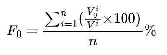
where Vi0 is the lug volume of the -th tooth when the die wheel feeds to 55% of the full tooth depth; Vi is the entire volume of the i-th tooth when the die wheel feeds to 55% of the full tooth depth; and n is the number of teeth.
4.3 Influence of Friction Coefficient on Lug
Based on the previous analysis, the friction forces on the two tooth surfaces towards the tooth tip lead to the formation of the lug defect, and the friction coefficient directly affects the friction force during rolling. This paper will focus on the influence law of the friction coefficient on the lug. By referring to the reference literature [18], the friction coefficients of 0.1, 0.2, and 0.3 are selected for the hot rolling forming simulation to explore the influence of the friction coefficient on the lug volume. Table 3 shows the friction coefficients of different lubricants under the condition of hot rolling steel.
| Lubricant Type | Rolling Temperature / °C | Friction Factor Range / Average Value |
|---|---|---|
| Spindle Oil + Additive | 950 – 1150 | 0.037 – 0.159 / 0.082 |
| Graphite | 950 – 1150 | 0.16 – 0.28 / – |
| Initial Heavy Oil | 950 – 1150 | 0.178 – 0.202 / 0.187 |
| Water | 950 – 1150 | 0.296 – 0.310 / 0.302 |
| No Lubricant | 950 – 1150 | 0.42 – 0.48 / 0.45 |
The proportions of the lug volumes corresponding to the three friction coefficients are shown in Table 4.
| Friction Coefficient | 0.1 | 0.2 | 0.3 |
|---|---|---|---|
| Lug Volume / % | 16.63 | 17.01 | 18.51 |
It is known from the relevant literature [18 – 20] that for face gears, spiral bevel gears, and helical bevel gears, as the friction coefficient increases, the lug volume shows an increasing trend. The reason is that the friction force is mainly related to the normal pressure and the friction coefficient. Under the conditions of unchanged rolling temperature, die wheel rotation speed, and die wheel feed speed, when the same die wheel rolls the face gear, the normal pressure changes little. When the friction coefficient increases, the friction force increases. Therefore, when the active side of the die wheel leaves the corresponding tooth surface of the gear blank, the friction force on the tooth surface increases, which will drive more tooth surface metal to flow towards the tooth tip, resulting in a stronger sharpening effect and an increase in the lug volume. It can be seen that the friction coefficient plays a promoting role in the formation of the lug. As the friction coefficient increases, the friction force exerted by the die wheel tooth surface on the gear blank tooth surface increases, resulting in an increase in the lug volume.
It can be seen from Table 4 that compared with the control group in this paper, the increase in the friction coefficient also leads to an increasing trend of the lug, which further verifies the effectiveness of the influence law of the friction coefficient on the lug volume of the spur cylindrical gear in this paper. Therefore, in the actual rolling process, the influence law of the friction coefficient on the lug obtained in this paper can provide a reference for the subsequent research.
5. Conclusions
In this paper, a rolling model of the spur cylindrical gear is constructed, and the variation laws of the equivalent stress field, equivalent strain field, and rolling force in the rolling forming process are analyzed. The law that the maximum strain occurs at the midpoint of the blank tooth profile and is biased towards the tooth root and the maximum stress is at the contact between the die wheel and the blank in each stage is clarified. The formation mechanism of the lug defect is studied, and the influence law analysis of the friction coefficient for the lug defect is realized, which provides a reference for the research on the rolling forming technology of the spur cylindrical gear.