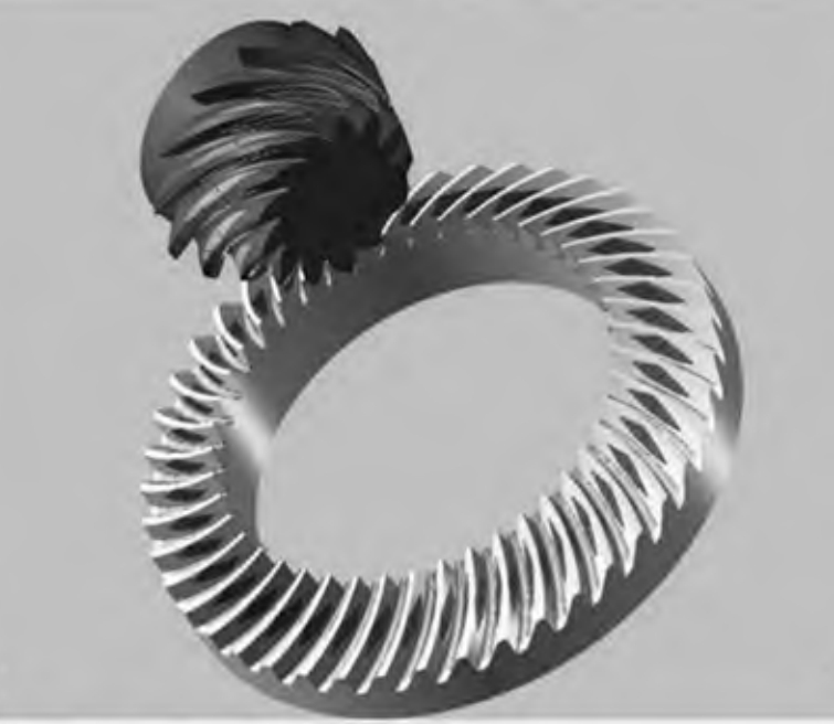
Abstract: The meshing process of spiral bevel gears using equivalent gear theory. A wear model for spiral bevel gears is established based on the Archard model. By comparing the wear amounts at various points on the mid-point normal section of the teeth, the critical points are identified. A reliability analysis of wear at these critical points is conducted. An extreme state function is established based on the Advanced First-Order Second-Moment (AFOSM) method. MATLAB programming is used to obtain the reliability and design points of the spiral bevel gears under selected design parameters. The effects of changes in working torque and speed on reliability are calculated. Monte Carlo simulation is employed for reliability analysis, and the results of both methods are close, indicating high efficiency and accuracy. This work provides a reference for reliability design and maintenance of spiral bevel gears.

Keywords: spiral bevel gear; wear; Archard model; reliability; AFOSM
1. Introduction
Spiral bevel gears are widely used in various mechanical equipment, such as automotive transmissions, industrial reducers, and marine transmission systems. Compared with ordinary gears, spiral bevel gears offer higher load capacity, lower noise and vibration, improved efficiency, and higher precision. However, prolonged operation can lead to wear and failure, reducing equipment reliability and lifespan. Therefore, reliability analysis of spiral bevel gear wear is crucial.
The following table summarizes existing research on gear wear reliability:
| Author | Research Focus | Methods |
|---|---|---|
| Zhou et al. | Adhesive wear on helical gear tooth surfaces under quasi-static and dynamic loads | Quantitative calculation and parameter analysis |
| ZHANG et al. | Planetary gear dynamics model and bearing wear calculation model for bearing life prediction | Dynamics modeling and wear calculation |
| DONG et al. | Gear wear calculation model under mixed elastohydrodynamic lubrication based on Kriging model | Kriging model-based wear calculation |
| YUAN et al. | Wear reliability analysis based on non-stationary stochastic process theory | Non-stationary stochastic process theory |
| Pan et al. | Reliability model of transmission accuracy considering dynamic wear for planetary reducers | Numerical simulation and stochastic process |
| Li | Reliability prediction for helicopter planetary gear transmission systems under eccentric loading | Reliability prediction |
| Zhang et al. | Fuzzy reliability calculation of gears based on abrasive wear principles | Fuzzy reliability calculation |
2. Simplification of Spiral Bevel Gear Model
Due to the complexity of spiral bevel gear geometry, equivalent gears can simplify the problem. The equivalent gears for spiral bevel gears are helical cylindrical gear pairs with pitch radii Rtanδ1 and Rtanδ2, tooth numbers z1/cosδ1 and z2/cosδ2, and a helix angle β.
3. Wear Calculation Model
3.1 Wear Rate Calculation
The Archard wear model relates wear volume V to sliding distance S, normal load W, surface hardness H, and wear coefficient K.
The basic formula is:
The wear rate Ih at any meshing point can be derived as:
For spiral bevel gears, the wear rate calculation is modified using equivalent gear theory.
3.2 Sliding Coefficient Calculation
Sliding coefficients λ1 and λ2 for the driving and driven gears are calculated based on the number of teeth in mesh and their velocities.
3.3 Wear Amount Calculation
The total wear amount h during gear operation is calculated using Hertz theory and the sliding distance.
4. Advanced First-Order Second-Moment (AFOSM) Method
The AFOSM method is a reliability design approach based on probability and statistics. It expresses system performance indicators as functions and performs Taylor expansions at failure points to determine design points.
Steps for AFOSM Calculation:
- Define the limit state equation Z = g(X) = 0.
- Perform Taylor expansion at point x* on the limit state surface.
- Calculate sensitivity coefficients and reliability index β.
- Iterate to find new x*.
- Check iteration conditions and repeat if necessary.
5. Reliability Analysis of Spiral Bevel Gear Wear
5.1 Limit State Function Establishment
To find the point of maximum wear on the mid-point normal section of the driving gear, the maximum and minimum pressure angles during one meshing cycle are calculated.
Table: Summary of Key Variables
| Symbol | Description |
|---|---|
| α | Gear pair pressure angle |
| αk1 | Pressure angle at meshing point on driving gear |
| β | Helix angle |
| δ1, δ2 | Cone angles of driving and driven gears |
| H | Surface hardness |
| Ih | Wear rate |
| K | Wear coefficient |
| λ | Sliding coefficient |
| n1 | Driving gear speed |
| p | Contact pressure |
| r | Radius |
| S | Sliding distance |
| t | Gear operation time |
| T | Torque |
| u | Equivalent transmission ratio |
| v | Relative sliding velocity |
| W | Normal load |
| X, x* | Random variables and design points |
| Z | Limit state function |
| αXi | Sensitivity coefficient |
| β | Reliability index |
| εα | Contact ratio |
| φ1, φ2 | Tooth width coefficients for driving and driven gears |
| zk1, zk2 | Contact point positions on driving and driven gears |
5.2 Reliability Analysis Results
Using AFOSM, the reliability and design points for the critical wear points on the spiral bevel gears are determined. The effects of working torque and speed on gear wear reliability are analyzed. Results are compared with Monte Carlo simulations, showing close agreement, validating the method’s efficiency and accuracy.
Conclusion
Rreliability analysis of spiral bevel gear wear based on the Archard model and AFOSM method. By simplifying the gear model and establishing a wear calculation model, the reliability of spiral bevel gears under different operating conditions is evaluated. The results provide a reference for reliability design and maintenance of spiral bevel gears, enhancing equipment lifespan and performance.
