
Abstract
This article focuses on the digital modeling and time-varying meshing characteristics analysis of hypoid gears processed by the Hypoid Face Tooling (HFT) method. By simulating the tool motion trajectory and deriving tooth surface equations, a mathematical model of the hypoid gear drive is established. Numerical algorithms and finite element analysis (FEA) are employed to investigate the meshing performance under different working conditions. The results provide insights into the transmission characteristics and dynamic behaviors of hypoid gears.
1. Introduction
Hypoid gears are widely used in various transportation tools such as vehicles, ships, aviation, and engineering machinery due to their small size, high transmission ratio, and strong carrying capacity. The HFT method, which involves a swing-type machine tool, is a commonly used processing method for hypoid gears in China. However, the theoretical tooth surface and tooth root transition surface equations are complex due to the additional tool rotation and tool inclination motions in the machine tool. Therefore, accurately reproducing the machining process and establishing a complete tooth surface model are fundamental for studying the meshing and transmission characteristics of hypoid gear pairs.
2. Mathematical Modeling of the HFT Machining Process
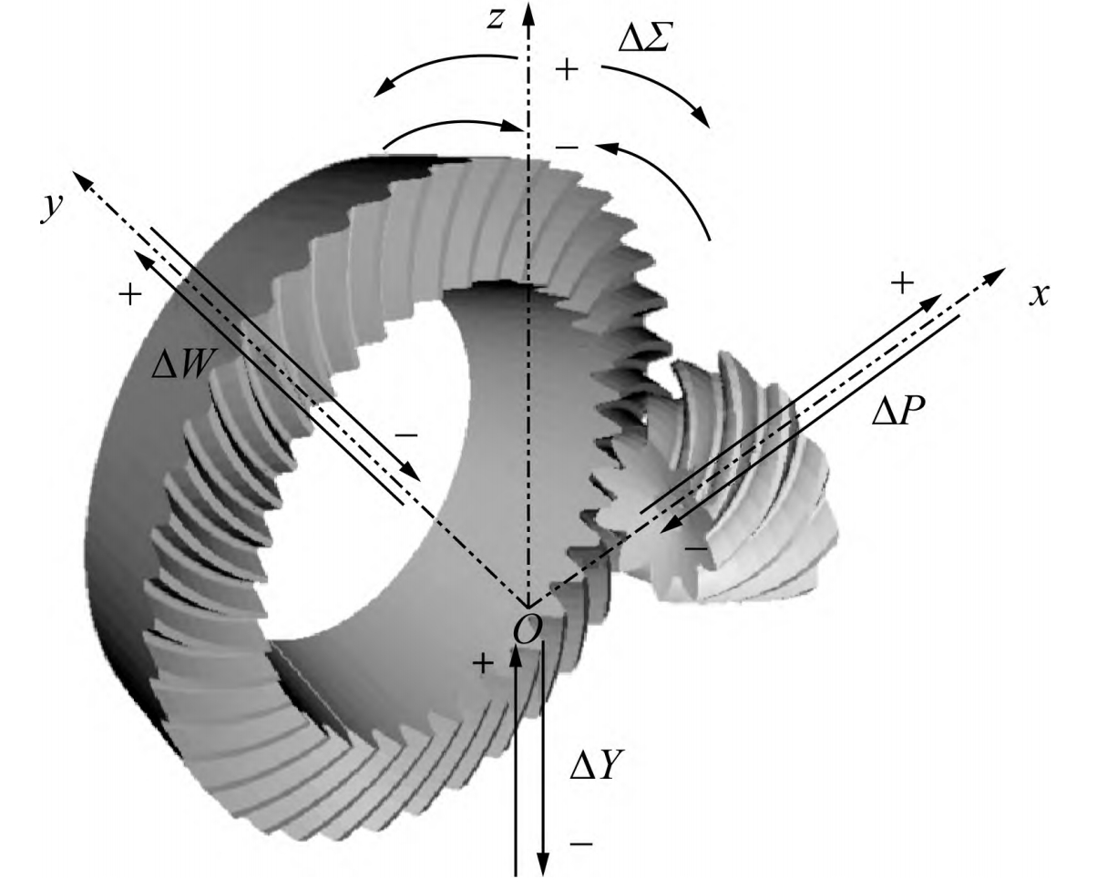
2.1 Coordinate System Definitions and Parameters
The following table summarizes the coordinate systems and associated parameters involved in the HFT machining process:
| Coordinate System | Definition | Involved Parameters |
|---|---|---|
| St2 | Tool disk coordinate system | Fixed to the large wheel milling cutter head |
| Sg | Tool disk transformation coordinate system | Cutter disk angle θg |
| Sa2 | Swing table transformation coordinate system | Radial tool position Sr2, angular tool position q2 |
| Sb2 | Bed transformation coordinate system | Bed position XB2 |
| Sc2 | Bed frame coordinate system | Vertical wheel position E2 |
| Sd2 | Root cone angle transformation coordinate system | Machine installation root cone angle δM2 |
| S2 | Gear blank coordinate system | Axial wheel position X2 |
2.2 Modeling of the Large Wheel Tooth Surface
The radial vector rg, normal vector Ng, and unit normal vector ng of a point G on the inner edge of the large wheel cutting tool disk in the Sg coordinate system are calculated as follows:
rg=((rG−ugsinα2)cosθg,(rG−ugsinα2)sinθg,−ugcosα2)
Ng=∂θg∂rg×∂ug∂rg
ng=∣Ng∣Ng=(−cosα2cosθg,−cosα2sinθg,sinα2)
These equations are transformed into the large wheel coordinate system S2 using homogeneous coordinate transformation matrices to obtain the theoretical tooth surface radial vector and normal vector equations.
2.3 Modeling of the Large Wheel Tooth Root Transition Surface
To protect the tool head during cutting and reduce tooth root bending stress, the tool tip usually has a transition fillet. The radial vector rg′ and unit normal vector ng′ of the tool tip fillet in the Sg coordinate system are calculated as follows:
rg′=((rG−ug0sinα2±rgfcosα2∓rgfsinγg)cosθg,…)
(The full equation includes sine and cosine terms similar to rg but with additional rgf and γg terms for the fillet.)
These equations are also transformed into the large wheel coordinate system S2 to obtain the tooth root transition surface equations.
3. Modeling of the Small Wheel Tooth Surface
The small wheel of the hypoid gear pair is processed using the HFT method, with concave and convex surfaces milled using different tool disks. The radial vector rp, normal vector Np, and unit normal vector np of a point P on the outer edge of the small wheel cutting tool disk in the Sp coordinate system are calculated similarly to the large wheel. These equations are then transformed into the gear blank coordinate system S1 using a series of homogeneous coordinate transformation matrices.
4. Tooth Contact Analysis (TCA)
The tooth surface equations derived in Sections 2 and 3 are discretized into three-dimensional point cloud coordinates. TCA is performed to obtain the static transmission error and contact pattern of the hypoid gear pair.
5. Finite Element Analysis (FEA)
The discrete point cloud coordinates of the tooth surfaces are used to construct a three-dimensional model of the hypoid gear pair in a finite element software such as ABAQUS. FEA is conducted to analyze the time-varying meshing characteristics of the hypoid gear pair under different working conditions, including dynamic meshing forces, tooth elastic deformations, meshing stiffness, and actual contact ratios.
6. Results and Discussion
The results show that the variation of load has a significant impact on the meshing force, transmission error, and meshing stiffness. With increasing load, the transmission error and meshing stiffness curves exhibit obvious asymmetric characteristics. These results provide a basis for the analysis of the transmission characteristics and dynamic behaviors of hypoid gears.
7. Conclusion
This article presents a comprehensive study on the digital modeling and time-varying meshing characteristics analysis of hypoid gears processed by the HFT method. By accurately reproducing the machining process and establishing precise tooth surface models, the meshing and transmission characteristics of hypoid gear pairs under different working conditions are investigated. The results obtained provide valuable insights for the design and optimization of hypoid gear transmissions.