
Abstract
This paper focuses on the meshing performance of hypoid gear pairs manufactured using the duplex helical method (also known as the full-process method). Numerical analysis is employed to investigate the interaction between installation errors, helical motion coefficients, and meshing performance. Mathematical models for gear cutting, tooth surface contact analysis (TCA), and tooth surface mismatch are established to analyze the contact characteristics and geometric morphologies. Experimental validation is conducted through gear grinding and rolling inspection, confirming the accuracy of the analytical models.
Keywords: duplex helical method; hypoid gear; installation error; meshing performance; tooth contact analysis; tooth surface mismatch
1. Introduction
Hypoid gears are widely used in power transmission mechanisms in aviation, automotive, and engineering machinery due to their advantages of high transmission ratio, high contact ratio, strong carrying capacity, smooth transmission, and high efficiency. However, obtaining optimal tooth surface contact characteristics is crucial for ensuring meshing performance.
2. Mathematical Models
2.1 Mathematical Model for Gear Cutting
The vector method is used to establish the mathematical model for gear cutting, which facilitates the derivation of the tooth surface equation. This foundation allows for the construction of a gear pair assembly model, enabling further analysis.
Table 1: Key Components of the Gear Cutting Model
| Component | Description |
|---|---|
| Tool Profile | Straight-line tool profile with a main working part (straight line) and a tooth root radius (arc) |
| Production Surface | Generated by the tool moving along a specified path |
| Coordinate Systems | Fixed to the tool, gear blank, and machine tool |
2.2 Tooth Surface Equation
The tooth surface equation is derived based on the gear cutting model, providing a detailed description of the tooth geometry.
2.3 Gear Pair Assembly Model
The gear pair assembly model integrates the tooth surfaces of both the pinion (small gear) and the gear (large gear), allowing for the analysis of tooth contact characteristics.
Figure 1: Gear Pair Modeling Process
<img src=”https://example.com/gear_pair_modeling_process.png” /> Note: This is a placeholder image; replace with the actual diagram.
3. Meshing Performance Analysis
3.1 Effect of Helical Motion Coefficient on Tooth Surface Contact and Geometry
The introduction of the helical motion coefficient in the duplex helical method allows for the pre-control of diagonal contact and contact trace length, improving meshing performance.
Table 2: Effects of Helical Motion Coefficient
| Helical Motion Coefficient | Effect on Work Surface | Effect on Non-Work Surface |
|---|---|---|
| Increasing | Moves contact trace towards small end and tooth tip | Moves contact trace towards large end and tooth tip |
| Decreasing | Moves contact trace towards large end and tooth root | Moves contact trace towards small end and tooth root |
3.2 Effect of Helical Motion Coefficient on Generating Line Position
The generating line, the cutting trajectory of the tool, significantly influences the microscopic morphology of the tooth surface.
Figure 2: Generating Line Schematic
<img src=”https://example.com/generating_line_schematic.png” /> Note: This is a placeholder image; replace with the actual diagram.
3.3 Influence of Installation Errors on Meshing Performance
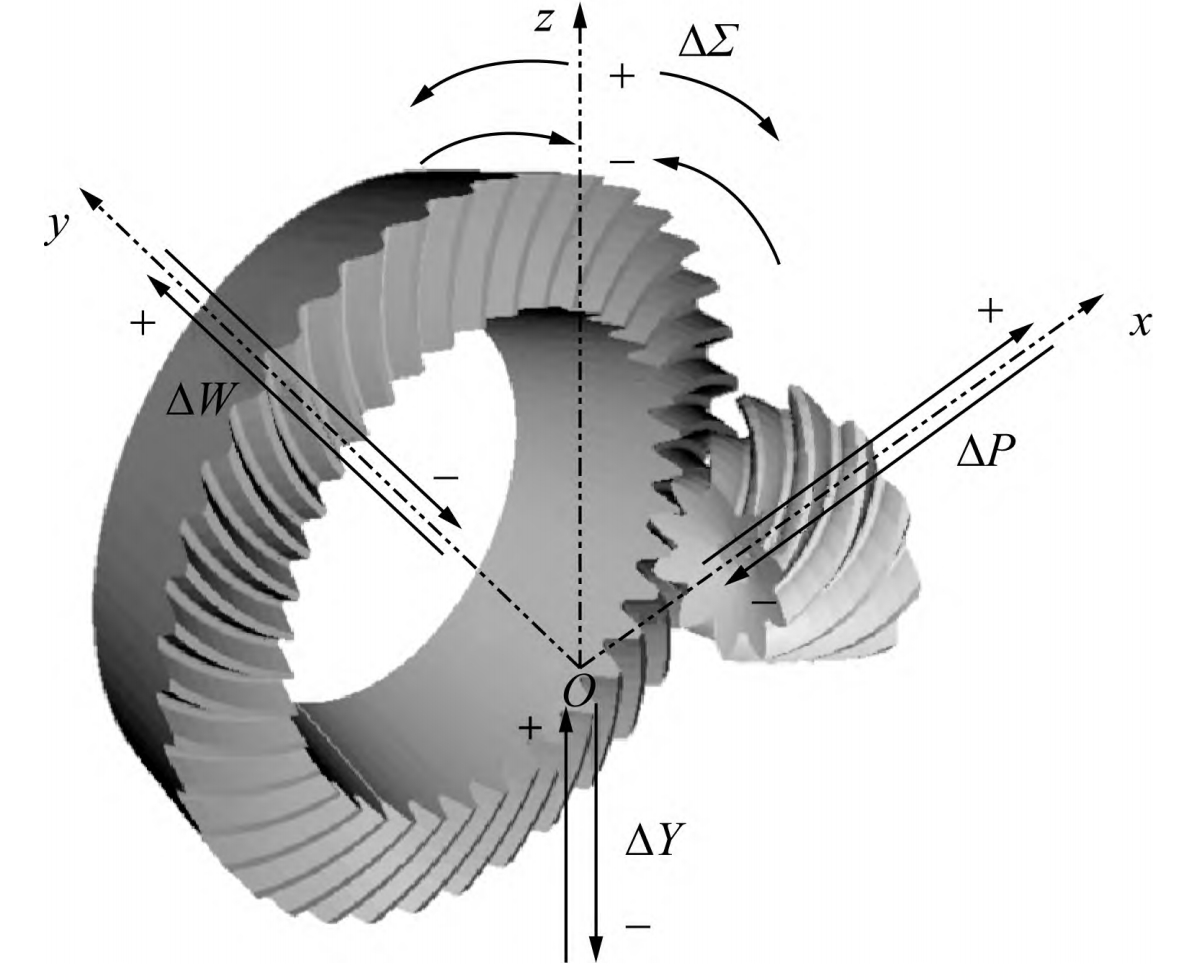
The meshing performance of hypoid gears is affected by installation errors, including pinion installation distance (∆H), pinion offset (∆V), gear installation distance (∆J), and shaft intersection angle (∆Σ).
Table 3: Adjustment Ranges for Installation Errors
| Error Type | Adjustment Range |
|---|---|
| Pinion Installation Distance (∆H) | −0.1 ~ 0.1 mm |
| Pinion Offset (∆V) | −0.1 ~ 0.1 mm |
| Gear Installation Distance (∆J) | −0.1 ~ 0.1 mm |
| Shaft Intersection Angle (∆Σ) | −0.5 ~ 0.5° |
Table 4: Effects of Installation Errors on Tooth Contact and Transmission Error
| Error Type | Effect on Work Surface Contact Trace | Effect on Non-Work Surface Contact Trace | Effect on Transmission Error (Work Surface) | Effect on Transmission Error (Non-Work Surface) |
|---|---|---|---|---|
| ∆H Increasing | Moves towards small end and tooth tip | Moves towards large end and tooth tip | Increases | Decreases |
| ∆H Decreasing | Moves towards large end and tooth root | Moves towards small end and tooth root | Decreases | Increases |
| ∆V Increasing | Moves towards small end and tooth tip | Moves towards large end and tooth tip | Decreases | Increases |
| ∆V Decreasing | Moves towards large end and tooth root | Moves towards small end and tooth root | Increases | Decreases |
| ∆J Increasing | Moves towards large end and tooth root | – | Increases | Increases |
| ∆J Decreasing | Moves towards small end and tooth tip | – | Decreases | Decreases |
| ∆Σ Increasing | Symmetrical change; contact length increases | Symmetrical change; contact length increases | Slightly increases | More significant increase |
| ∆Σ Decreasing | Symmetrical change; contact length decreases | Symmetrical change; contact length decreases | Slightly decreases | More significant decrease |
4. Experimental Validation
To further validate the role of helical motion in controlling diagonal contact and contact trace length, actual processing of the designed hypoid gear pair was performed using an H350G CNC spiral bevel gear grinding machine. The gear pair was then inspected on a rolling test machine under specific conditions.
Figure 3: Tooth Grinding and Contact Patterns
<img src=”https://example.com/tooth_grinding_and_contact_patterns.png” /> Note: This is a placeholder image; replace with the actual diagram.
5. Conclusion
- Mathematical models for gear cutting, tooth surface contact analysis, and tooth surface mismatch were established.
- The effects of installation errors and helical motion coefficients on tooth surface contact characteristics and transmission errors were studied.
- The different modification principles for the work and non-work surfaces during processing were revealed.
- Experimental validation confirmed the accuracy of the models and the effectiveness of helical motion in controlling diagonal contact and contact trace length.