
Abstract: This paper proposes a geometric design method for hypoid gears with small cross angles, derives the geometric relationships of the spatial pitch cone pair based on the instantaneous axis of the uniparted hyperboloid pair, and puts forward a control method for the meshing characteristics of hypoid gear pairs with small cross angles considering smooth tooth root transition. Gear pair meshing models and finite element analysis models are established to study the influence of different external loads on the meshing characteristics. A prototype of the hypoid gear transmission with a small cross angle verifies the smooth operation of the hypoid gear under extreme geometric scales with small cross angles.
1. Introduction
Spatial gears with small cross angles can overcome the problems of complex structures, low efficiency, and high costs associated with power steering under extreme conditions, featuring small size, high transmission accuracy, and high reliability. They have irreplaceable advantages and broad application prospects in areas such as high-speed ship propulsion angle transmission and four-wheel drive automotive power distribution angle transmission. The existing spatial transmission components with small cross angles are mainly involute variable-thickness gears and hypoid gears. Compared to involute variable-thickness gears, hypoid gears offer advantages such as large contact ratio, pre-settable meshing characteristics, and unrestricted single-wheel pitch cone angle, making them widely used in orthogonal spatial transmissions. However, in the field of small cross-angle spatial transmissions, the extreme variations in parameters such as cross angle and offset distance complicate the tooth profile evolution and meshing mechanism, rendering traditional design methods for hypoid gears based on orthogonal installations unsuitable and severely limiting their development and application.
The following table summarizes the current research status of hypoid gears with small cross angles:
| Researcher | Contribution |
|---|---|
| DOONER et al. | Proposed the concept of applying hypoid gears in small cross-angle transmissions. |
| STADTFELD | Conducted preliminary derivation of geometric parameters for hypoid gears with small cross angles. |
| YANG et al. | Conducted preliminary exploration of machining parameter calculation methods for hypoid gears with small cross angles based on the local synthesis method. |
| LIU et al. | Discussed the range of basic geometric parameters for hypoid gears with small crossing angles and created a closed graph. |
| DOONER | Proposed a design method for hypoid gears suitable for 0° to 90° conditions based on generalized involute curves. |
2. Geometric Design of Hypoid Gears with Small Cross Angles
The relative motion in spatial crossed-axis transmissions is helical. When the generatrix of the imaginary tooth surface blank rotates around the gear rotation axis, a pair of uniparted hyperboloids is formed, as shown in Figure 1. The contact area of the two uniparted hyperboloids is defined as the instantaneous contact axis.
The distance between the rotation axes of the two uniparted hyperboloids is defined as E, the cross angle between the two axes is defined as Σ, and the ratio of the rotational speeds of the two uniparted hyperboloids is m21.
Based on the uniparted hyperboloid pair, a pitch cone pair model satisfying the same working conditions can be established. As shown in Figure 3, the small pitch cone Ω1 and the large pitch cone Ω2 are in contact at the reference point M.
The following table summarizes the first geometric relationship of hypoid gears with small cross angles:
| Geometric Relationship | Formula |
|---|---|
| First Geometric Relationship | cosβm12 = tanγm1tanγm2 + cosΣcosγm1cosγm2 |
The second geometric relationship can be derived based on the relative velocity at the tangent point M:
| Geometric Relationship | Formula |
|---|---|
| Second Geometric Relationship | i12 = rm2cosβm2 / rm1cosβm1 |
Based on the pitch cone pair model, the spatial geometric relationship of hypoid gears with small cross angles can be established. As shown in Figure 4, the third geometric relationship can be derived:
| Geometric Relationship | Formula |
|---|---|
| Third Geometric Relationship | E = sinβm12sinΣ(rm1cosγm2 + rm2cosγm1) |
The limit pressure angle and limit curvature can also be derived based on the above geometric relationships.
3. Optimization of Local Synthesis Method for Face-Milling Hypoid Gears with Small Cross Angles
The machining of hypoid gears with small cross angles relies on existing milling machines. The tooth surface generation mechanism is shown in Figure 6.
The tool disk and the tooth surface’s spatial position are controlled through nine machining parameters of the machine tool for the small gear based on the generating method, completing the tooth surface generation process. For the large gear tooth surface based on the forming method, it is controlled through five machining parameters.
The relationship between the rocker’s angular velocity ωp, the tool disk’s angular velocity ωt, and the gear blank’s angular velocity ωc is as follows:
| Relationship | Formula |
|---|---|
| Angular Velocity Relationship | ωp/ωc = Zi/Zp, ωp/ωt = Z0/Zp |
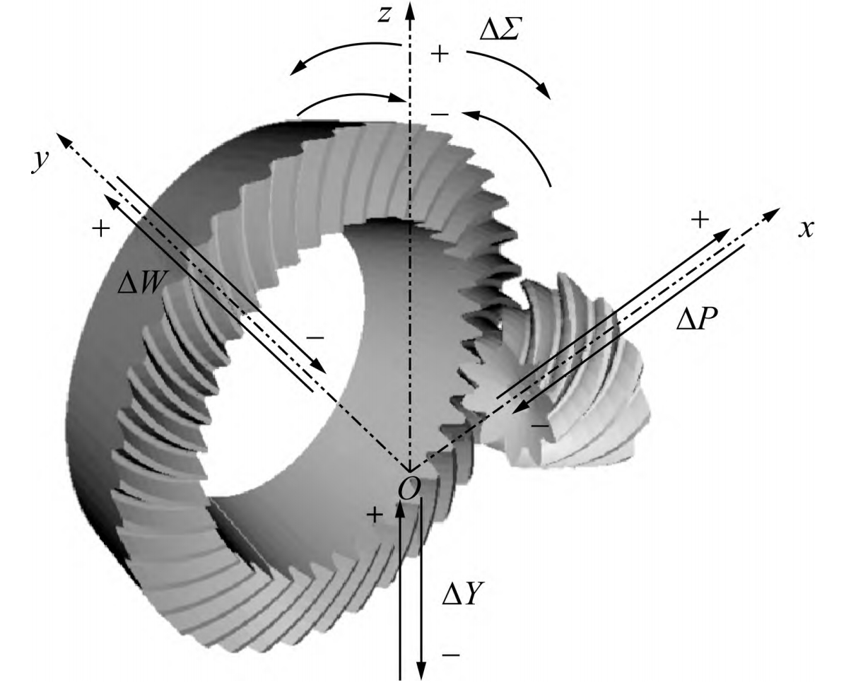
The local synthesis method is a method of known large gear tooth surface, and the target small gear machining parameters are calculated backward by presetting the position of the only conjugate point and three meshing characteristic control parameters.
In summary, this paper provides a comprehensive geometric design method and meshing characteristic