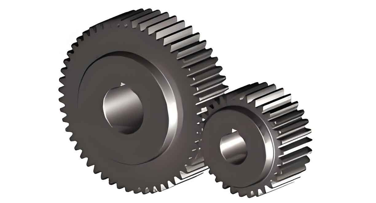
Abstract: Rolling forming technology can significantly improve the utilization rate of metal materials and enhance the fatigue strength of gears. This paper focuses on the rolling forming process of spur gear, deriving tooth surface equations, realizing tooth surface point calculation, and utilizing DEFORM software for simulation. The study analyzes equivalent stress fields, equivalent strain fields, and changes in rolling forces. The formation mechanism of lug defects during rolling is explored, and the influence of friction coefficients on lugs is investigated. The optimization of friction coefficients for lug control is achieved, providing a theoretical foundation for the rolling forming of spur gear.

1. Introduction
Spur gear is crucial components for transmitting motion and power. Traditional gear processing methods such as hobbing, shaping, milling, and turning can disrupt metal flow lines, severely weakening the fatigue strength of gears. Gear rolling near-net-shape technology is a plastic forming manufacturing process that relies on forced meshing between the die wheel and the workpiece blank to form the tooth shape. The intact metal flow lines can effectively increase the fatigue strength of gears, thereby extending their service life.
2. Literature Review
Previous research on gear rolling forming technology has yielded significant results. Table 1 summarizes some key studies in this field.
| Author | Research Focus | Main Findings |
|---|---|---|
| WEI et al. | Deformation, heating, and microstructure evolution in cross-wedge rolling | Average grain size and dynamic recrystallization volume fraction distribution analyzed |
| YUAN et al. | Influence of worm rotation on tooth surface hardness, strain distribution, and flow line distribution | Hardness, strain, and flow line distribution analyzed |
| NISTOR et al. | Deformation mechanisms and gear geometry parameter effects on straight gears | Good-quality spur gear obtained |
| SIECZKAREK et al. | Factors affecting first tooth filling deficiencies in incremental forming | Friction, blank cutting process, edge properties, and process strategy optimization studied |
| Others | Rolling process parameters, material flow laws, and other aspects | Various aspects of gear rolling forming studied |
3. Establishment of Gear Rolling Equivalent Model
3.1 Derivation of Tooth Surface Equation
The tooth surface equation for a standard involute spur gear is derived as follows:
r_a (θ_s, u_a) = [X_a, Y_a, Z_a]
= [±r_b sin(θ + θ_s) – θ_s cos(θ + θ_s), -r_b cos(θ + θ_s) + θ_s sin(θ + θ_s), u_a]
where:
- r_b is the base circle radius;
- θ_s is the parameter of the involute;
- ± indicates the left or right involute;
- u_a is the axial position coordinate parameter of the gear tooth surface.
3.2 Rolling Model Construction
The rolling process of gears can be divided into three stages: preliminary tooth splitting, tooth forming, and tooth finishing.
Table 2 lists the basic parameters of the target gear and mold gear used in this study.
| Parameter | Target Gear | Mold Gear |
|---|---|---|
| Modulus (mm) | 2 | 2 |
| Addendum coefficient | 1 | 1 |
| Pressure angle (°) | 20 | 20 |
| Top clearance coefficient | 0.25 | 0.25 |
| Number of teeth | 19 | 53 |
4. Numerical Simulation Model Establishment
The numerical simulation model for gear rolling is established using DEFORM software. The main deformation areas of the wheel blank are refined to improve simulation accuracy. The boundary conditions and process parameters are set based on actual working conditions.
5. Numerical Simulation Analysis of Straight Gears
5.1 Hot Rolling Gear Forming Analysis
Simulations are conducted for different feed depths (12%, 30%, 60%, 100%). The hot rolling forming process.
The equivalent strain distribution during the rolling process is analyzed. Maximum strain occurs at the midpoint of the tooth profile towards the tooth root. The equivalent strain at different feed depths.
The rolling force, a dynamic quantity, is analyzed. It increases with feed depth and shows significant fluctuations due to changes in metal friction and resistance. Tthe variation of rolling forces in the X, Y, and Z directions.
6. Lug Formation Mechanism and Control
6.1 Lug Formation Mechanism
The formation of lugs is analyzed through force analysis. The main pressure N from the die wheel on the workpiece tooth surface is the primary factor promoting tooth shape formation. Frictional forces f towards the tooth tip cause lug defects.
6.2 Lug Evaluation Criteria and Measurement Method
An evaluation criterion for lugs is established based on the proportion of lug volume to total tooth volume. The influence of friction coefficients on lug volume is investigated. Table 3 summarizes the lug volume with different friction coefficients.
| Friction Coefficient | Lug Volume (%) |
|---|---|
| 0.1 | 16.63 |
| 0.2 | 17.01 |
| 0.3 | 18.51 |
Table 3. Lug volume with different friction coefficients
The results show that an increase in friction coefficient leads to an increase in lug volume, validating the influence law of friction coefficient on lug formation.
7. Conclusion
This paper constructs a rolling model for spur gear, analyzes the variation laws of equivalent stress fields, equivalent strain fields, and rolling forces, clarifies the maximum strain and stress locations, studies the formation mechanism of lug defects, and realizes the optimization of friction coefficients for lug control. The findings provide a reference for research on spur gear rolling forming technology.
