
Abstract
With the rapid development of the automotive industry, precision forming of gears has become an inevitable trend in the forging industry. This paper focuses on the precision forming process development for a commonly used large module and large size spur gear part in heavy-duty vehicles, aiming to achieve the precision forming of external spur gear.
1. Introduction
The forging of spur gear teeth can ensure complete and continuous metal flow lines in the tooth area, resulting in better tooth strength than machining, while also saving material and reducing production costs. However, large module and large size spur gear face challenges such as poor filling at the tooth corners, difficult ejection, and low mold life. This paper presents a precision forming process for such spur gear.
2. Part and Equipment Selection
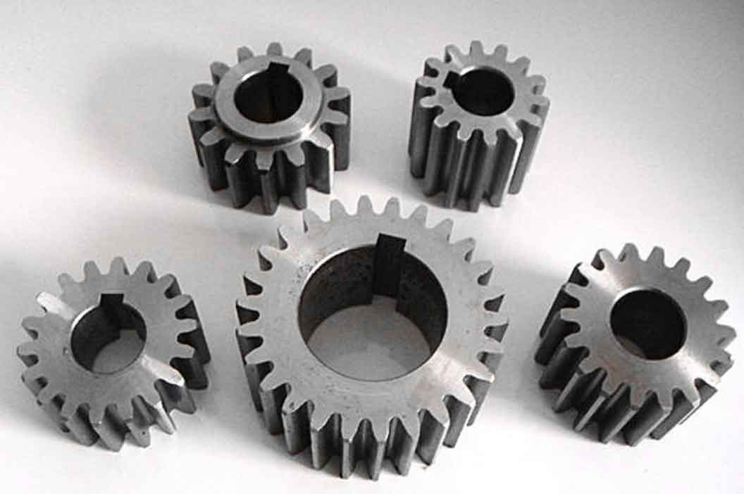
2.1 Part Diagram
The maximum outer diameter of this part is φ248mm, with a tooth width of 58mm, a module of 5.22mm, and 46 teeth, making it a typical large module and large size spur gear part.
| Parameter | Value |
|---|---|
| Outer Diameter (mm) | 248 |
| Tooth Width (mm) | 58 |
| Module (mm) | 5.22 |
| Number of Teeth | 46 |
2.2 Forging Blank Diagram
A 1mm allowance is left on one side of the tooth area, and a 1.3mm allowance is left on the other sides. An ejection angle of 0.5° is taken at the outer circle.
2.3 Equipment Selection
The formula for calculating the forming force is P = (50~70)F, where F is the projected area of the forging (cm²). Considering the complexity of the forging, a coefficient of 70 is selected, resulting in a calculated P of approximately 3.44×10⁶ kN. Based on practical experience, the nominal force of the equipment should be about 1.2 times greater than the deformation force, calculating to 4128 tons. Ultimately, a 6300-ton hot die forging press is selected.
3. Mold Design and Deform-3D Simulation
3.1 Design Ideas
Due to the weight of the forging blank (about 14kg) and the large number of teeth, if the preforming includes teeth, it will be difficult to quickly and accurately place the preformed blank into the final forging cavity, leading to rapid cooling of the tooth area and poor filling during final forging. Therefore, the preforming process is simplified and does not include tooth shapes. The preforming to final forging is positioned by the tooth root circle, and the final forging adopts a floating structure with a large ejector pin in the center or a ring ejector to ensure stable ejection of the forging.
| Mold Component | Description |
|---|---|
| Preforming Upper Mold | Simple material distribution without tooth shapes |
| Final Forging Mold | Tooth shapes formed with a floating structure |
| Ejection Mechanism | Large ejector pin in the center or ring ejector |
3.2 Deform-3D Simulation
Due to the large tooth width and the large amount of material used in the tooth area, more material is required at the outer contour during material distribution. Therefore, the volume of the material in the middle should be reduced as much as possible during preforming design. The preforming to final forging is positioned by the tooth root circle. Through multiple Deform-3D simulations, the forming scheme is finally determined. When the striking force is 4896 tons, the tooth area of the forging is fully filled.
4. Actual Production and Result Analysis
Graphite lubrication is selected for actual production, with a forging temperature of 1200°C. The preformed blank and final forged blank are shown in Figures 6 and 7, respectively. During the forging process, positioning from preforming to final forging is stable by the tooth root circle, and ejection is smooth using the center ejector. The final production results are basically the same as the simulation results, with good filling in the tooth area. The lower part of the overall tooth width is better filled than the upper part due to the 0.5° ejection angle, which allows for more machining allowance on the upper part and reduces waste rates.
5. Conclusion
The following conclusions are drawn from the precision forming process development for large module and large size spur gear through analysis of mold structure, allowance, equipment selection, Deform-3D simulation, and production verification:
- For large module and large size spur gear forgings, it is not recommended to design tooth shapes during preforming. This increases mold costs and leads to rapid cooling of the tooth area, making it difficult to quickly place the preformed blank into the final forging cavity and resulting in poor filling. Therefore, simplifying the preforming process design and relying on the tooth root circle for positioning is sufficient.
- Due to the large tooth width and large tooth area contact with the mold, a ring ejector near the outer circle or a large center ejector pin should be used to ensure stable ejection of the forging.
- When selecting forging equipment for complex tooth structures, the equipment should have a capacity at least 1.2 times greater than the deformation force to avoid overload and damage.
- The material temperature should be controlled at around 1200°C during production. Lower temperatures significantly affect the filling of the tooth area and increase waste rates.
- The tooth mold experiences high forces, so mold material should be selected reasonably to avoid failure due to cracking during forging.