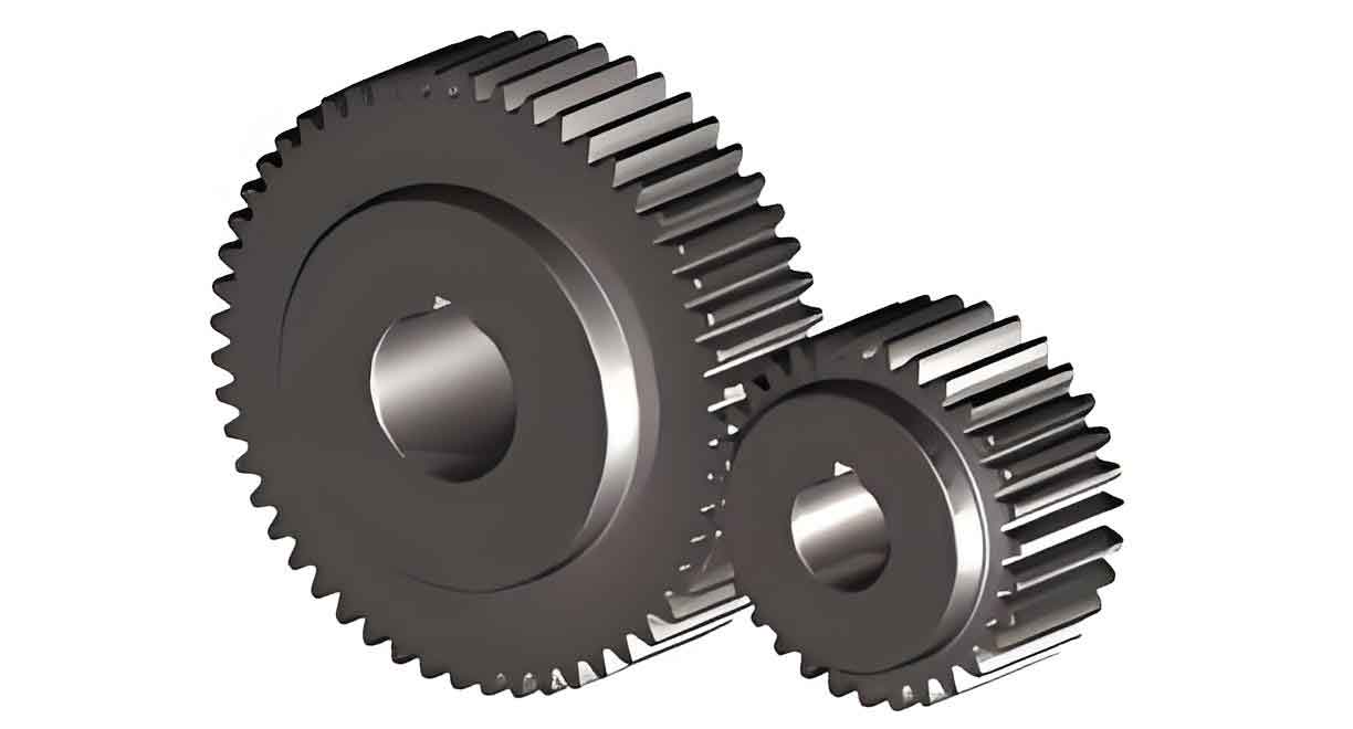
The vibration characteristics of spur gear transmission systems with root cracks. An improved dynamic simulation method is proposed to account for the uneven distribution of tooth root cracks. The following content summarizes the key findings and methodologies of the study using tables and figures.

1. Introduction
Spur gear transmission systems are widely used in aerospace, marine, and rail transportation due to their high efficiency, compact structure, and reliability. However, gear faults, particularly tooth root cracks, pose a significant threat to the safety and stability of machinery. To address this, a comprehensive study on the vibration characteristics of spur gear with root cracks is conducted.
2. Dynamic Model of Spur Gear Pair with Root Crack
2.1 Model Description
The dynamic model of the spur gear pair considered in this study includes five degrees of freedom for both spur gear and the pinion: longitudinal (X), vertical (Z), yaw (φ), roll (β), and pitch (ψ) motions. Spur gear and pinion are treated as a single body with their mass and moment of inertia concentrated at the centroid. Bearings are also modeled with simplified spring-damper elements.
| Components | Degrees of Freedom | Description |
|---|---|---|
| Gear/Pinion | X, Z, φ, β, ψ | Longitudinal, Vertical, Yaw, Roll, Pitch |
| Bearings | Simplified spring-damper | Supporting the gear and pinion |
2.2 Mesh Stiffness Model with Root Crack
To calculate the mesh stiffness of spur gear with unevenly distributed root cracks, the “slicing method” is employed. Spur gear is divided into several thin slices along the tooth width, and each slice is modeled as a two-dimensional cantilever beam with a variable cross-section.
| Parameters | Description |
|---|---|
| K_t, K_f, K_h | Tooth stiffness, fillet base stiffness, Hertz contact stiffness |
| K_b, K_s, K_a | Bending stiffness, shear stiffness, axial stiffness |
| E, G | Young’s modulus, Shear modulus |
| I_x, A_x | Cross-sectional moment of inertia, Cross-sectional area |
The mesh stiffness (K_m) of each gear slice is calculated using the following formula:
2.3 Mesh Force and Contact Force Model
Due to the uneven distribution of root cracks, the mesh stiffness varies across different gear slices, resulting in uneven mesh forces. The mesh forces are calculated considering both longitudinal and vertical relative displacements.
| Force Components | Description |
|---|---|
| F_X, F_Z | Longitudinal and Vertical Mesh Forces |
| T_φ, T_ψ | Roll and Yaw Moments |
The contact forces between the outer ring and the bearing seat are also calculated to understand the vibration response of the bearings.
3. Simulation Analysis
3.1 Vibration Response of Bearings
The dynamic response of spur gear transmission system is simulated under steady-state conditions. The main design parameters of spur gear is listed in Table 1.
| Symbol | Parameter | Value |
|---|---|---|
| M | Modulus (mm) | 8 |
| α_r | Pressure Angle (°) | 20 |
| Z | Number of Teeth | 120 (Gear), 23 (Pinion) |
| W | Tooth Width (mm) | 136 (Gear), 175 (Pinion) |
| E | Young’s Modulus (GPa) | 200 |
| υ | Poisson’s Ratio | 0.3 |
The simulation results show that the vibration responses, including roll and yaw accelerations, are sensitive to the uneven distribution of cracks. The maximum roll acceleration amplitude is 53.8 rad/s², and the maximum yaw acceleration amplitude is 19.6 rad/s².
3.2 Statistical Analysis of Vibration Data
Statistical indicators, such as kurtosis (K_u) and impulse factor (I_f), are used to analyze the severity of cracks along the tooth width.
| Statistical Indicator | Description |
|---|---|
| Kurtosis (K_u) | Measures the peakedness of the vibration signal |
| Impulse Factor (I_f) | Measures the impulsiveness of the vibration signal |
The results indicate that both kurtosis and impulse factor exhibit a parabolic trend during crack propagation, consistent with the dynamic analysis findings.
4. Conclusion
This study proposes an improved dynamic simulation method for spur gear transmission systems with unevenly distributed tooth root cracks. The model reveals that uneven cracks cause asymmetric mesh forces, generating unbalanced moments and affecting vibration characteristics. The simulation results show that the vibration response of the bearing on the side where the crack initiates is more intense and increases with crack length. Statistical analysis of vibration data further confirms the model’s effectiveness in monitoring crack propagation.
The proposed model provides a theoretical basis for the detection and diagnosis of tooth root cracks in spur gear, enhancing the safety and reliability of machinery.
