Abstract
The meshing process of spiral bevel gears using equivalent gear theory and establishes a wear model based on the Archard model. Wear reliability analysis is conducted on critical points, and the limit state function is established using the Advanced First-Order Second-Moment (AFOSM) method. MATLAB programming is utilized to obtain the reliability and design point of spiral bevel gears under selected design parameters. The influence of changes in working torque and speed on reliability is calculated, and Monte Carlo simulation is employed for reliability analysis. The results of both methods are close, indicating high efficiency and accuracy. This work provides a reference for reliability design and maintenance of spiral bevel gears.
1. Introduction
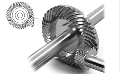
Spiral bevel gears are widely used in various mechanical equipment such as automotive transmissions, industrial reducers, and marine transmission systems. Due to their complexity and time-varying meshing process, there is a lack of research on wear reliability for spiral bevel gears. This paper aims to analyze the wear reliability of spiral bevel gears based on the Archard model and AFOSM method, validated by Monte Carlo simulation.
Table 1: Overview of Research on Gear Wear Reliability
| Author | Research Focus | Model Used | Methodology |
|---|---|---|---|
| Zhou et al. | Wear of helical gears under quasi-static and dynamic loads | Quantitative calculation and parameter analysis | Experimental and theoretical |
| ZHANG et al. | Wear prediction of planetary gear bearings | Dynamics model and wear calculation model | Modeling and simulation |
| DONG et al. | Wear calculation under mixed elastohydrodynamic lubrication | Kriging model | Modeling and simulation |
| YUAN et al. | Wear reliability analysis based on non-stationary random process theory | Non-stationary random process theory | Theoretical analysis |
| Pan et al. | Reliability model considering dynamic wear for planetary reducers | Numerical simulation | Simulation |
| Li | Reliability prediction for helicopter planetary gear systems under partial load | Reliability prediction | Theoretical and experimental |
| Zhang et al. | Fuzzy reliability calculation based on abrasive wear principle | Fuzzy reliability method | Theoretical analysis |
2. Simplification of Spiral Bevel Gear Model
To simplify the complex geometry of spiral bevel gears, equivalent gear theory is used. The equivalent gears have a pitch radius of Rtanδ1, Rtanδ2, tooth numbers of z1/cosδ1, z2/cosδ2, and a helix angle of β.
Table 2: Parameters of Equivalent Gear
| Parameter | Description | Symbol |
|---|---|---|
| Pitch radius | Radius of the pitch circle | Rtanδ1, Rtanδ2 |
| Tooth number | Number of teeth | z1/cosδ1, z2/cosδ2 |
| Helix angle | Angle of the helix | β |
3. Wear Numerical Calculation Model
3.1 Wear Rate Calculation
The Archard wear model relates wear volume to contact pressure, sliding distance, and material hardness. The basic formula is:
VS = KWH
Where V is wear volume, S is sliding distance, W is normal load, H is surface hardness, and K is the wear coefficient.
Table 3: Wear Rate Calculation Parameters
| Parameter | Description | Symbol |
|---|---|---|
| Wear rate | Rate of material removal | Ih |
| Wear coefficient | Dimensionless coefficient | k = K/H |
| Contact pressure | Pressure at the contact point | p |
| Sliding speed | Relative speed at the contact point | v |
3.2 Sliding Coefficient Calculation
The sliding coefficients for the driving and driven gears are calculated based on the number of teeth in mesh and their respective velocities.
Formula for Sliding Coefficient
λ1 = 1 + (1/u) * (1 – (tanα / tanαk1))
λ2 = (1/u) * (1 + u * tanα – tanαk1) / ((1 + u) * tanα – tanαk1)
3.3 Wear Volume Calculation
The total wear volume is calculated by integrating the wear rate over the total sliding distance during the operation time.
Formula for Total Wear Volume
h = πn1²(u+1)²k1T(tanαk1 – tanα)²tεα³φ1mz²v²tanαk1 / (30H)
4. Advanced First-Order Second-Moment (AFOSM) Method
4.1 Limit State Equation
The limit state equation is expressed as:
Z = g(X) = 0
4.2 Taylor Series Expansion
At a point x* on the limit state surface, the Taylor series expansion is used to linearize the limit state equation.
Formula for Linearized Limit State Equation
ZL = g(X(x)) + Σ (∂g(X(x))/∂Xi) * (Xi – x*i)
4.3 Reliability Index
The reliability index β is the distance from the origin to the tangent plane (limit state surface) at the design point A.
Formula for Reliability Index
β = μZL / σZL
Table 4: Parameters for Reliability Analysis
| Parameter | Description | Symbol |
|---|---|---|
| Limit state function | Function defining the limit state | g(X) |
| Design point | Point on the limit state surface | x* |
| Sensitivity coefficient | Direction cosine of the design point | αXi |
| Mean of ZL | Mean value of the linearized limit state function | μZL |
| Standard deviation of ZL | Standard deviation of the linearized limit state function | σZL |
5. Reliability Analysis and Results
The reliability of the spiral bevel gear under selected design parameters is calculated using MATLAB. The influence of changes in working torque and speed on reliability is analyzed. Monte Carlo simulation is employed to validate the results.
Table 5: Reliability Analysis Results
| Parameter | Value |
|---|---|
| Reliability index (β) | [Calculated Value] |
| Design point (x*) | [Coordinates of x*] |
| Influence of torque on reliability | [Description] |
| Influence of speed on reliability | [Description] |
6. Conclusion
Method for wear reliability analysis of spiral bevel gears based on the Archard model and AFOSM method. The results are validated by Monte Carlo simulation, showing high efficiency and accuracy. The proposed method provides a reference for reliability design and maintenance of spiral bevel gears.
