
Abstract
The high cost and limited versatility of specialized machines and cutter heads used in the current manufacturing process of helical bevel gears. A method employing a flat bottom milling cutter on a general five-axis machine tool for helical bevel gear machining is proposed. By utilizing gear meshing and envelope machining principles, a parametric model of the helical bevel gear is constructed. The roughing, semi-finishing, and finishing trajectories for both sides of the gear using flat bottom milling cutter end milling and side milling are planned. Tooth surface machining simulations are carried out on the obtained tool trajectories. The results demonstrate a relatively uniform machining surface, achieving helical bevel gear processing on five-axis machine tools, which enhances the versatility and economy of large-scale or single-piece small-batch gear processing.
1. Introduction
Helical bevel gears are fundamental transmission components for transmitting motion and power between intersecting axes. They are widely used in aviation, navigation, automotive, and other industries due to their strong load-bearing capacity, low noise, and high transmission efficiency. Currently, helical bevel gear machining primarily involves the use of specialized machines and cutter heads for tooth surface cutting. However, for single-piece small-batch processing or larger-sized gear processing, imported specialized machines and cutter heads are expensive and not very versatile. With the development of five-axis CNC machine tool technology, it has become feasible to use five-axis machines for helical bevel gear tooth surface machining. However, different trajectory planning methods can generate different issues when using five-axis machines for curved surface cutting, necessitating in-depth research into tooth surface machining trajectory planning.
The following table summarizes the research background and current status:
| Researcher | Methodology | Key Findings |
|---|---|---|
| Tian Guofu et al. | Gear meshing and envelope machining principles | Accurate output of tooth surface point coordinates and acquisition of helical bevel gear tooth surface parameters |
| Wang Yongsheng et al. | Spherical involute theory | Precise modeling of gears through solving various curves and tooth line equations on the end tooth profile |
| Wang Zhenyu | Ball-end milling cutter for tooth surface processing | Determination of the optimal vector position through continuous cutting adjustment during actual production |
| Zhang Ning | Calculation of the tooth flank conversion index angle | Manufacturing of a special large-scale zero-degree helical bevel gear forming milling cutter |
| Wang Chaotai et al. | Using UG platform for CAD and CAM | Planning of tool machining trajectories using spherical milling cutters |
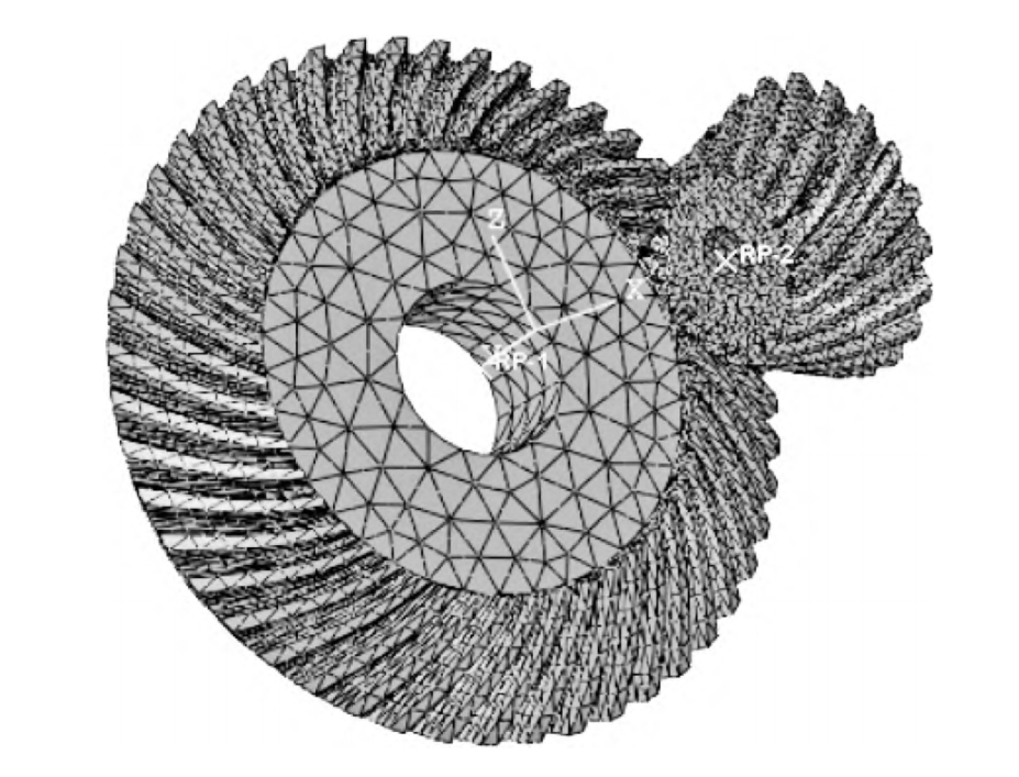
2. Tooth Surface Equation of Helical Bevel Gear
2.1 Establishment of the Equation
Based on the traditional swing-table helical bevel gear machine tool structure, various coordinate systems from the cutter head to the gear are established. Through spatial coordinate transformation, the envelope of the tool on the gear blank forms the teeth, obtaining the tooth surface equation in the gear coordinate system.
2.2 Discretization of the Tooth Surface
By limiting the range of tooth surface variables, the tooth surface data points are solved. The tooth surface is projected onto its axial cross-section and divided into m columns in the tooth length direction and n rows in the tooth height direction, forming m×n grid points. The two-dimensional coordinates (Xij, Yij) of the grid points are solved through positional relationships.
The following table lists the basic parameters of a selected set of helical bevel gears:
| Parameter | Value (Small Wheel/Large Wheel) |
|---|---|
| Number of teeth | 15 / 28 |
| Module (m) | 6 mm |
| Tooth width (b) | 25 mm |
| Hand of helix | Right-hand / Left-hand |
| Pressure angle (α) | 20° |
| Shaft intersection angle (Σ) | 90° |
3. Trajectory Planning for Tooth Surface Machining
3.1 Spatial Coordinate System Position
The workpiece coordinate system S’2 is obtained by transforming the aforementioned gear motion coordinate system S2. The tool coordinate system S1 coincides with the workpiece coordinate system, with the origin at the tool clamping point position in the machine tool.
3.2 Calculation of General Pose Tool Axis
In five-axis CNC machining, a local coordinate system for general tool axis control is established, including pitch angle α and tilt angle γ. At the tool location point p, a local coordinate system (fn, n, v) is established; n represents the surface normal direction; fn represents the feed direction.
3.3 Rough Machining Tool Location Points and Tool Axis Vectors
Rough machining removes most of the material allowance, preparing for subsequent machining. Gleason gears have tapered teeth, with the tooth slot width at the large end being greater than at the small end, and the tooth slot width at the root cone being smaller than at the face cone. Therefore, the machining trajectory needs to be planned.
Tool Location Point Calculation:
The data points in the nth row of the tooth surface discrete data points represent the theoretical maximum cutting depth position of the tooth slot. The data points are offset by the minimum distance tp_min along the normal of the root cone, and the middle point after offsetting is taken as the tool location point at the maximum cutting depth.
Tool Axis Vector Calculation:
Rough machining is performed with the tool axis perpendicular to the root cone surface. The resulting rough-machined surface is parallel to the root cone surface, with layered cutting ensuring consistent cutting depths between each layer.
3.4 Semi-finishing and Finishing
Semi-finishing removes the material allowance at the tooth root and ensures uniform allowance. During finishing, the number of tool location points is increased, and the tool feed pitch is reduced to decrease the surface roughness, completing the helical bevel gear machining and ensuring a uniform machined surface.
Tool Location Point Calculation:
Side milling with the side edge of the flat bottom milling cutter is performed. The fitted curves are parameter lines, and the data points for the offset tooth surface are calculated as coordinates with equal step lengths.
Tool Axis Vector Calculation:
Both semi-finishing and finishing use side edge machining, with the tool axis vector parallel to the surface to be machined and perpendicular to the normal direction.
4. Simulation of Tooth Surface Machining Trajectories
To verify the effectiveness of the helical bevel gear tooth surface machining trajectory planning proposed in this paper, machining trajectory simulations were performed using the parameters in Table 2.
4.1 MATLAB Tooth Surface Machining Trajectory Simulation
The gear tooth surface data points are calculated using Equations (1) to (4). The rough machining tool location points and tool axis vectors are determined using Equations (7) to (10). The semi-finishing and finishing tool location points and tool axis vectors are determined using Equations (11) to (14).
4.2 VERICUT Tooth Surface Machining Trajectory Simulation
The helical bevel gear large wheel tooth surface machining simulation was performed in the VERICUT software, with model parameters consistent with the previous ones. The SINUMERIK 840D was added as the numerical control system.
The following table summarizes the comparison results:
| Comparison Criteria | Result |
|---|---|
| Machined tooth surface uniformity | Relatively uniform |
| Overcut and residue marks | No large-scale overcut and residue marks (some marks caused by chip breaking) |
5. Conclusion
The establishment of helical bevel gear model, plans roughing, semi-finishing, and finishing tooth surface machining trajectories using different specifications of flat bottom milling cutters, and conducts tooth surface machining simulations on MATLAB and VERICUT software. The conclusions are as follows:
- A tooth surface equation is established based on gear meshing and envelope machining principles, and the helical bevel gear model is established by solving tooth surface data points through an iterative method.
- Based on the calculated tooth surface data points and the positional relationship between the tool and the tooth surface during machining, the tool location points and tool axis vectors for roughing, semi-finishing, and finishing are calculated. Tooth surface machining can be performed according to the planned trajectories, with a relatively uniform machined surface.
- Using the method in this paper for helical bevel gear tooth surface machining enhances versatility and reduces processing costs, providing a new approach for large-scale or single-piece small-batch helical bevel gear machining.