Abstract:
The tooth-skipped meshing process within the context of gear honing, particularly focusing on external-meshing gear honing. By segmenting the process into standard involute helicoid meshing and addendum meshing, a comprehensive analysis is conducted based on spatial geometry and gearing principles. Three-dimensional (3D) models are established for both meshing processes to identify contact points and their corresponding relationships on the tooth surfaces. A method to determine the transition points between these processes is also proposed, leveraging the geometric relationship between the skip-tooth worm and the gear.

Keywords: tooth-skipped meshing; three-dimensional simulation; relative speed; gear overall error; gear honing; addendum meshing
1. Introduction
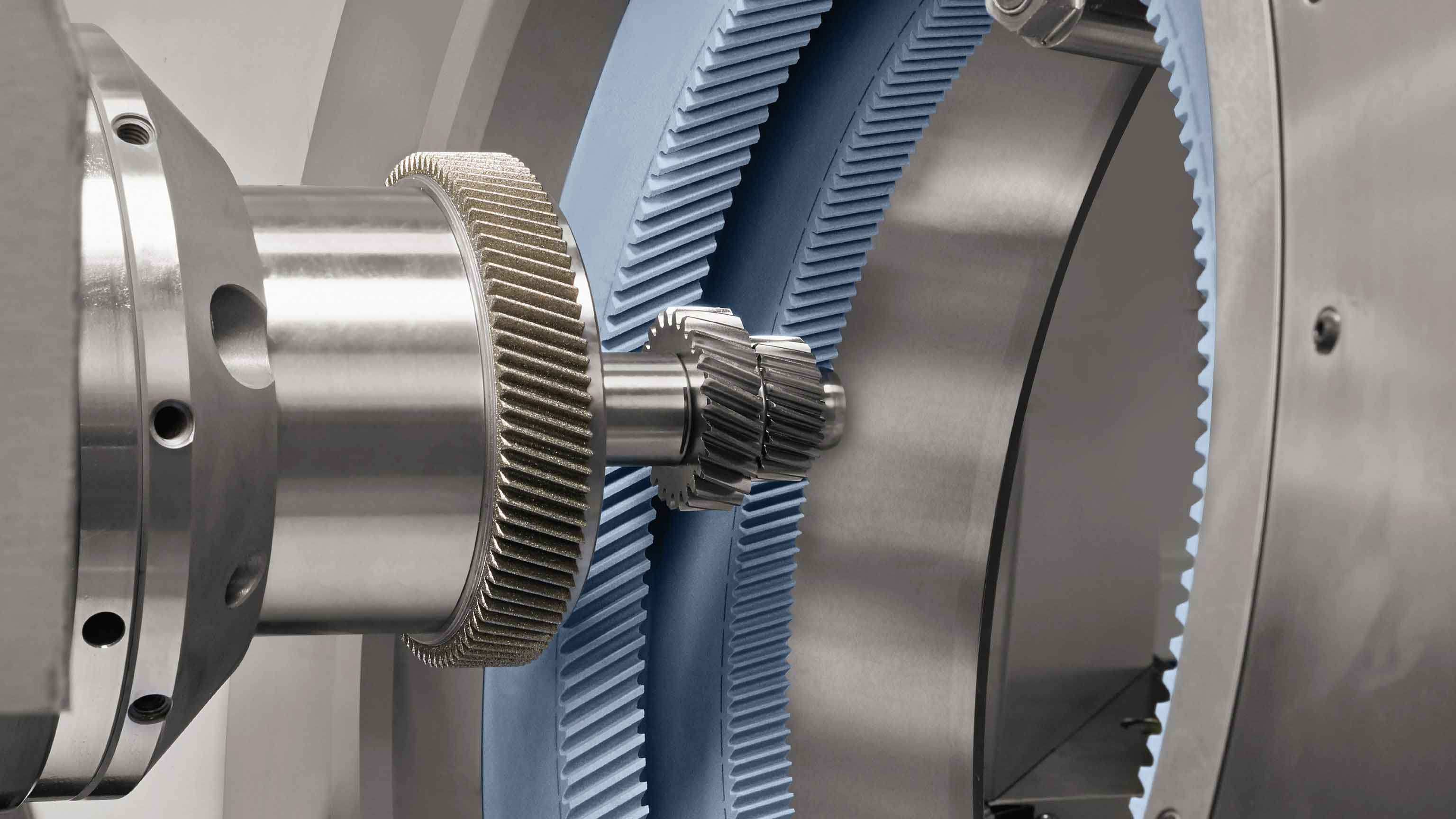
Gear honing is a precision machining process widely used to improve the tooth profile shape, helix accuracy, and surface finish of gears, thereby reducing noise, enhancing wear resistance, and prolonging gear lifespan. Among the various honing techniques, external-meshing gear honing stands out due to its simple machine structure and lower cost. However, it is not as widely adopted as internal-meshing gear honing primarily because it tends to produce concave tooth profiles. To address this issue, the research team led by Shi Zhaoyao introduced the tooth-skipped gear honing method based on the tooth-skipped meshing principle.
2. Overview of the Tooth-Skipped Meshing Principle
The tooth-skipped meshing principle was introduced alongside the technology for measuring overall gear errors. In this principle, a skip-tooth worm is used for measurement, where only one tooth is functional during meshing, with the others thinned out to prevent engagement. This ensures that only one tooth contact occurs during the entire measurement process, defining the tooth-skipped meshing process.
The two-dimensional tooth-skipped meshing process can be divided into three stages: gear addendum meshing (K1K2), standard involute meshing (K2K3), and rack addendum meshing (K3K4). Similarly, the three-dimensional process also consists of these stages, but with the engaging elements transitioning from planar curves to spatial surfaces.
Table 1: Comparison of 2D and 3D Tooth-Skipped Meshing Processes
| Dimension | Gear Addendum Meshing | Standard Involute Meshing | Rack Addendum Meshing |
|---|---|---|---|
| 2D | K1K2 | K2K3 | K3K4 |
| 3D | Spatial curve on tooth top | Spatial involute helicoid | Spatial curve on worm top |
3. Calculation of Contact Points in Tooth-Skipped Meshing
3.1 Standard Involute Helicoid Meshing Process
This process involves the meshing of crossed-axis involute helical gears. During this process, the worm and the gear rotate at a constant transmission ratio. According to Litvin’s research, the normal line at the contact point, i.e., the line of action, passes through the tangent point T on the working pitch cylinder.
Equation (4):
⎩⎨⎧Xc−xTc=xn1c(Zc−zTc)Yc−yTc=yn1c(Zc−zTc)Zc−zTc=zn1c(Zc−zTc)
Where (xTc,yTc,zTc) are the coordinates of point T in coordinate system Sc, and (xn1c,yn1c,zn1c) is the direction vector of the normal to the tooth surface of the worm at the contact point.
3.2 Addendum Meshing Process
In tooth-skipped meshing, both gears undergo addendum meshing. Assuming the worm rotates actively, the gear addendum meshing occurs before standard involute helicoid meshing, where the gear tooth tip scrapes the worm tooth surface. Conversely, worm addendum meshing occurs after standard involute helicoid meshing.
4. Determination of Transition Points in Tooth-Skipped Meshing
Each stage of tooth-skipped meshing has transition points, totaling four: the starting point of gear addendum meshing, the starting point of involute helicoid meshing, the ending point of involute helicoid meshing, and the ending point of worm addendum meshing. These points can be categorized into two types: those related to the starting point of involute helicoid meshing and those related to the starting point of addendum meshing.
Table 2: Transition Points and Their Correspondence
| Worm Angle | Gear Angle | Correspondence |
|---|---|---|
| φ11 | φ24 | Gear addendum meshing start |
| φ12 | φ23 | Involute helicoid meshing start (worm) |
| φ13 | φ22 | Involute helicoid meshing end (gear) |
| φ14 | φ21 | Worm addendum meshing end |
5. Three-Dimensional Simulation of Tooth-Skipped Meshing
To better understand the tooth-skipped meshing process, a 3D simulation is conducted using specific worm and gear parameters. The models established earlier are solved using C++ programming, and the results are displayed.
5.1 Contact Point Trace on Tooth Surface
By solving the 3D tooth-skipped meshing model using C++, discrete coordinates of the contact point trace on the tooth surface are obtained. These coordinates are imported into simulation software to generate a 3D plot of the contact point trace.
5.2 Relative Speed
Calculating the relative speed at the contact point aids in understanding the gear honing mechanism. The direction of the relative speed determines the grinding section position, and the ratio of the components of the relative speed along this direction on both tooth surfaces can be used in the G. Wener grinding force model to calculate the grinding force at the contact point.
5.3 Gear Overall Error Unit Curve
The tooth-skipped meshing principle originated from gear overall error measurement technology. This model can establish the overall error unit curve, which is the theoretical curve during the overall error measurement process. Each tooth corresponds to a unit curve during tooth-skipped meshing.
6. Conclusion
The tooth-skipped meshing process in external-meshing gear honing. By segmenting the process into standard involute helicoid meshing and addendum meshing, 3D models were established to identify contact points and their correspondences. The transition points between these processes were determined using geometric relationships. A 3D simulation was conducted to visualize the contact point trace, analyze relative speeds, and establish the gear overall error unit curve, validating the model’s accuracy. The insights gained from this research contribute to a deeper understanding of the tooth-skipped gear honing mechanism and can guide the design and optimization of honing processes for gears.
