Abstract
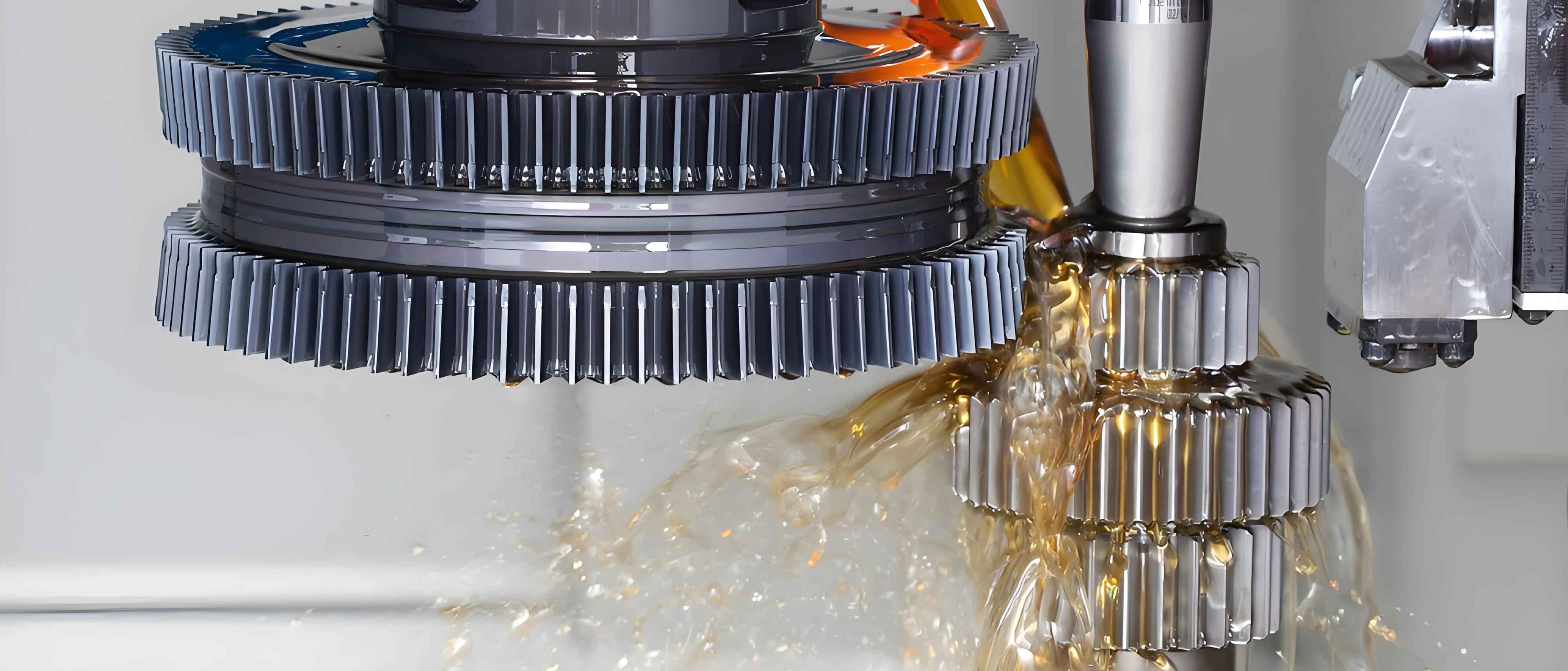
The gear shaping process for the rigid wheel of harmonic drive reducers, proposing an optimizable gear shaping scheme. Typical anomalies encountered during this process are analyzed, explained, and specific solutions are provided.

1. Introduction
Harmonic drive reducers are precision transmission components that utilize a wave generator to assemble with a flexible structure and a rigid wheel. The rigid wheel, as the direct meshing transmission part, features small-modulus, multi-tooth, and high-precision internal teeth. Gear shaping is a critical process for manufacturing the rigid wheel, with stringent requirements on gear shaping tools, the precision of semi-finished rigid wheels, tooling fixtures, and positioning.
2. Structure and Characteristics of the Rigid Wheel
2.1 Structure Overview
The rigid wheel of the harmonic drive reducer used in this study is made of ductile iron and includes multiple structures such as fixing holes, sealing grooves, stepped end faces, and tooth profiles.
| Structure | Function | Precision Requirement |
|---|---|---|
| Fixing Hole | Fixation and connection | High |
| Sealing Groove | Prevents leakage | Moderate |
| Stepped End Face | Positioning and bearing support | High |
| Tooth Profile | Meshing transmission | μ-level precision |
2.2 Processing Difficulties
The primary challenge in manufacturing the rigid wheel lies in the processing of its internal tooth profiles, which require μ-level precision. This is affected by factors such as the precision of the gear shaping cutter and the processing technology.
3. Gear Shaping Process Plan
3.1 Process Overview
The process begins with basic structure removal through turning, drilling, and milling operations.随后, the coaxiality of the inner and outer circles and their perpendicularity to the end faces are ensured to obtain qualified semi-finished rigid wheels. Finally, internal tooth processing is carried out using a gear shaping machine.
| Process Step | Equipment Used | Precision Requirement |
|---|---|---|
| Material Removal | Lathe, Drill Press, Milling Machine | As per design |
| Semi-finishing | Precision Lathe | High |
| Gear Shaping | High-precision Gear Shaping Machine | μ-level precision |
3.2 Equipment and Measurement
High-precision numerical control gear shaping machines and high-precision gear measurement centers are used, capable of measuring involute gears, non-standard gears, etc.
4. Analysis and Handling of Abnormalities in the Gear Shaping Process
4.1 Analysis of Clamping Force and Tooth Pitch Anomalies
4.1.1 Error Sources
The main errors in gear shaping originate from three sources: machine tool transmission chain errors, fixture positioning errors, and tool errors.
| Error Source | Impact on Gear Shaping |
|---|---|
| Machine Tool Transmission Chain | Precision of tooth form and pitch |
| Fixture Positioning | Precision of tooth form and pitch |
| Tool Errors | Precision of tooth profile |
4.1.2 Clamping Force Analysis
Research on the inner diameter of the rigid wheel and the screw clamping force was conducted to analyze and summarize the torque range of the screw clamping force N.
| Inner Diameter (mm) | Clamping Force (N/m) |
|---|---|
| X1 | 0.5 |
| X2 | 0.8 |
| X3 | 1.0 |
| X4 | 2.3 |
Through the least squares method, a linear relationship between the inner diameter and the clamping force was obtained: y = 0.044x – 15.
4.1.3 Solutions
The clamping force should be effectively controlled within a torque range of ±0.3 N/m to ensure that the rigid wheel’s tooth form and tooth pitch errors remain within acceptable limits.
4.2 Analysis of Cutter Installation Precision and Tooth Pitch Anomalies
4.2.1 Cutter Precision Impact
The precision of the gear shaping cutter directly determines the precision of the tooth profile, and the tooth pitch of the cutter is also a major factor affecting the tooth pitch of the rigid wheel.
4.2.2 Installation and Adjustment
When installing the gear shaping cutter, the taper shank of the cutter mates with the taper shank of the tool holder and is tightened with screws. The other end of the tool holder is securely fastened to the C-axis of the machine spindle. To ensure precision, the eccentricity between the cutter and the C-axis of the machine spindle must be minimized.
4.2.3 Solutions
Automatic programs can be developed to achieve uniform rotation of the C-axis at a certain speed, facilitating accurate readings. By adjusting the position of the cutter and tool holder and using a dial indicator to confirm the eccentricity, the eccentricity of the cutter can be controlled.
4.3 Analysis and Handling of Top Land Burrs and Abnormal Tooth Profile Measurements
4.3.1 Top Land Burr Formation
During continuous gear shaping, small burrs may form at the intersection of the tooth tip and tooth side, affecting the smooth movement of the measuring pin during tooth profile measurement.
4.3.2 Measurement Anomalies
When using a small-diameter measuring pin to measure the tooth profile trajectory of the rigid wheel, it does not closely follow the tooth, failing to smoothly transition at the tooth tip entry position.
4.3.3 Solutions
Existing burrs on the rigid wheel can be manually removed with sandpaper. Additionally, the gear shaping program can be optimized by increasing the stroke value of the cutter and reducing the circumferential feed value of the tooling fixture, objectively reducing the formation of burrs on the tooth tip.
5. Conclusion
By analyzing and controlling factors such as clamping force, cutter installation precision, and top land burrs, the errors in the tooth form and tooth pitch of the rigid wheel can be effectively controlled within the desired precision level. Multiple batches of qualified harmonic drive reducer rigid wheels have been processed, with quality tending to be stable.
To achieve a mature process for mass production, continuous efforts from equipment developers, process researchers, and other engineering personnel are required. It is also recommended to purchase cutters with a full-top-cut design to avoid generating excessive burrs from the source.
The above research provides a valuable reference for the optimization of the gear shaping process for the rigid wheel of harmonic drive reducers, contributing to the development of more stable and precise manufacturing technologies.
