
Abstract
The research of fully numerical control vertical gear milling machines, particularly on the coordinate control method and software development for spiral bevel gear cutting and measurement. By integrating online measurement functions and tooth profile error adjustment, this study aims to provide support for the closed-loop production mode of bevel gears in China.
1. Introduction
With the increasing demand for high-speed, high-precision, and dry-cutting spiral bevel gear processing, the fully numerical control vertical gear milling machine has emerged as a new type of equipment that meets these requirements. However, the research on this type of machine in China is still in its early stages. Therefore, it is necessary to propose a motion control method and develop corresponding control software for the vertical gear milling machine.
2. Structure and Motion Analysis of Fully Numerical Control Vertical Gear Milling Machine
The vertical gear milling machine has a high rigidity due to its workpiece spindle perpendicular to the horizontal plane, and better chip flow. The following table summarizes the main components and their functions:
| Component | Function |
|---|---|
| Workpiece spindle | Holds the workpiece and rotates during the cutting process |
| Tool spindle | Holds the cutting tool and moves along multiple axes to form the desired tooth profile |
| NC system | Controls the motion of the tool spindle and workpiece spindle based on input parameters |
3. Research on Cutting Motion Coordinate Control Method
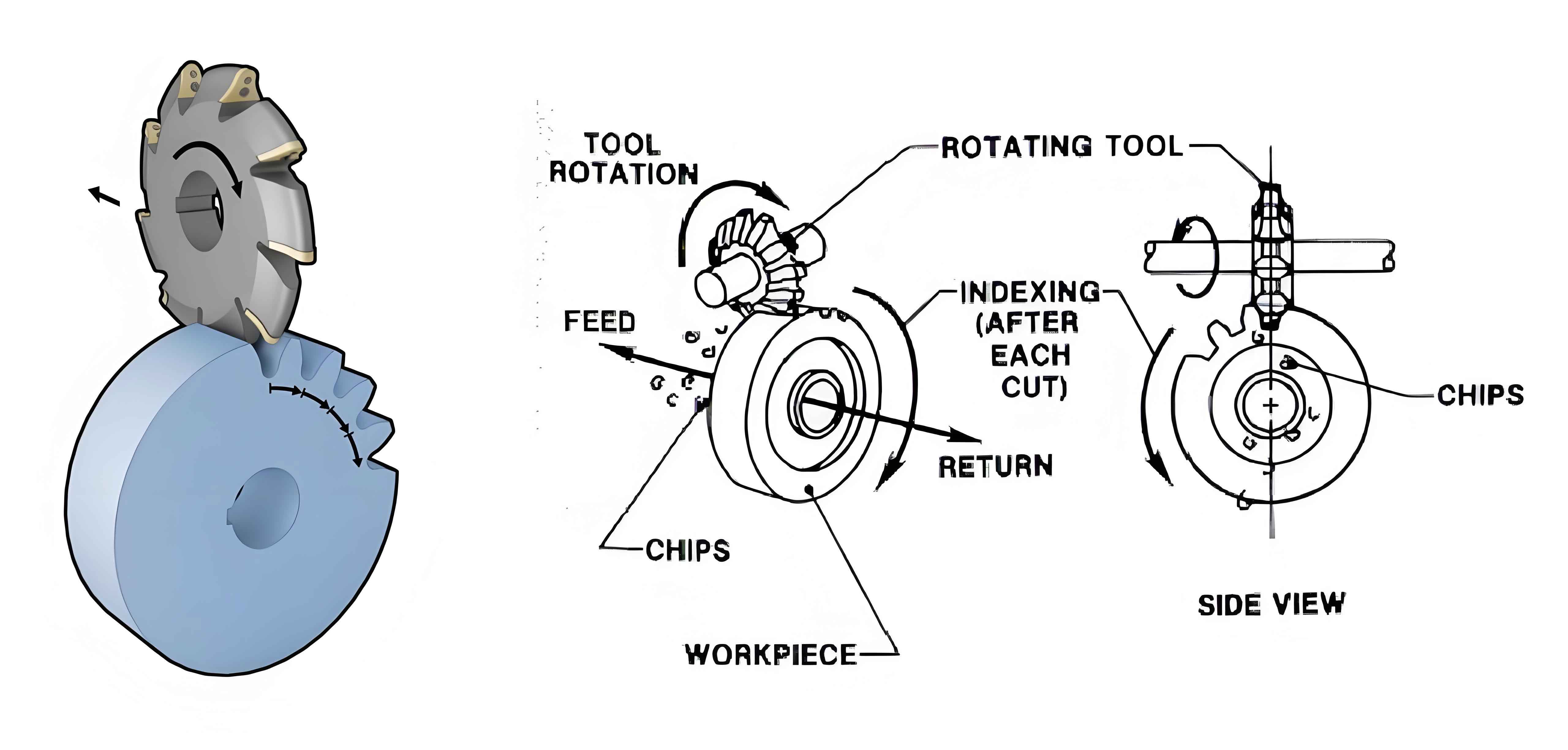
3.1. Cutting Principle and Machine Motion Analysis
The cutting principle of spiral bevel gear and the structure characteristics of the vertical gear milling machine are analyzed to establish the motion model during the cutting process. The relationship between the tool and the workpiece, as well as their motion rules, is clarified.
3.2. Tool Path Calculation
Based on the established motion model, the tool path for cutting spiral bevel gear is calculated. The following table shows the key parameters involved in the calculation:
| Parameter | Description |
|---|---|
| Tool adjustment parameters | Parameters that adjust the position and orientation of the tool |
| Gear parameters | Parameters that define the geometry of the gear |
| Machine parameters | Parameters that define the motion capabilities of the machine |
3.3. Conjugate Contact Point Calculation
To ensure the accuracy of the tooth profile, the conjugate contact points between the tool and the workpiece are calculated. This involves complex geometric calculations and the use of advanced mathematical models.
4. Research on Measurement Motion Coordinate Control Method
4.1. In-Machine Measurement Principle
The in-machine measurement principle is based on the use of a measuring probe to measure the tooth profile of the gear after cutting. The selection and installation of the measuring mechanism, as well as the establishment of the measurement motion model, are crucial steps in this process.
4.2. Measurement Path Planning and Error Quantification
The measurement path of the measuring probe is planned to ensure comprehensive coverage of the tooth profile. The errors are then quantified and graded based on the measurement results.
4.3. Tooth Profile Error Adjustment
The tooth profile errors are parameterized and analyzed using advanced mathematical methods. The following table summarizes the key steps in the tooth profile error adjustment process:
| Step | Description |
|---|---|
| Error parameterization | Converting tooth profile errors into mathematical parameters |
| Error surface analysis | Analyzing the geometric characteristics of the error surface |
| Constraint conditions | Applying constraints based on the tooth root geometry |
| Optimization function | Establishing an optimization function to minimize the tooth profile errors |
5. Development of Control Software for Fully Numerical Control Vertical Gear Milling Machine
5.1. Software Planning
The software is designed to monitor the cutting process, manage processing data and files, and communicate with the NC system. The following table summarizes the main software functions:
| Function | Description |
|---|---|
| Process monitoring | Monitoring machine axis positions, cutting angles, and other critical parameters |
| Data management | Creating, editing, importing, and exporting processing data files |
| Communication | Communicating with the NC system to send and receive control commands |
5.2. Communication between NC Software and Machine
The software communicates with the NC system using the SINUMERIK Operate programming suite. The following table summarizes the key communication interfaces:
| Interface | Description |
|---|---|
| FileSvc | For file operations, such as reading and writing |
| DrivesService | For monitoring and controlling drive-related information |
5.3. Key Algorithm Implementation
The software includes key algorithms for calculating tool paths, measuring grid points, and writing measurement data back to the machine. The following table summarizes the main algorithm functions:
| Algorithm | Description |
|---|---|
| Tool path calculation | Calculating the tool path based on input parameters |
| Measurement grid point division | Dividing the tooth surface into grid points for measurement |
| Data writing back | Writing measurement data back to the machine for further processing |
6. Simulation and Verification
To verify the correctness of the theoretical derivations and software algorithms, simulation experiments were conducted. The results showed that the proposed motion control method and software can accurately control the cutting and measurement processes of the vertical gear milling machine.
7. Conclusion
The motion control method and develops corresponding control software for the fully numerical control vertical gear milling machine. The research achieves the motion control of the machine, integrates online measurement functions, and proposes a tooth profile error adjustment method. However, there is still room for improvement in terms of monitoring functions, communication capabilities, and in-machine measurement functions. Future work will focus on integrating the error adjustment program into the software and conducting further testing and verification on the actual machine.