
Abstract
This paper first compares the process differences in gear honing for two MQ series automotive transmission gears. It then introduces the common defect types and causes of gear honing in batch production. To address these honing defects, two process route improvement methods are proposed. One method involves using a shaving process before heat treatment to remove burrs and high points on the tooth surface (with minimal change to the gear dimensions), which is used to solve pre-inspection failures of gear honing machine. The other method uses the shaving process before heat treatment for preliminary tooth surface shaping of the pre-honing blanks (changing the gear dimensions), addressing issues such as sandwheel breakage, dark patches on the tooth surface, unqualified precision measurement reports, and pre-inspection failures. Both methods have been experimentally verified and partially applied in batch production, showing significant effects on improving honing efficiency and processing quality.
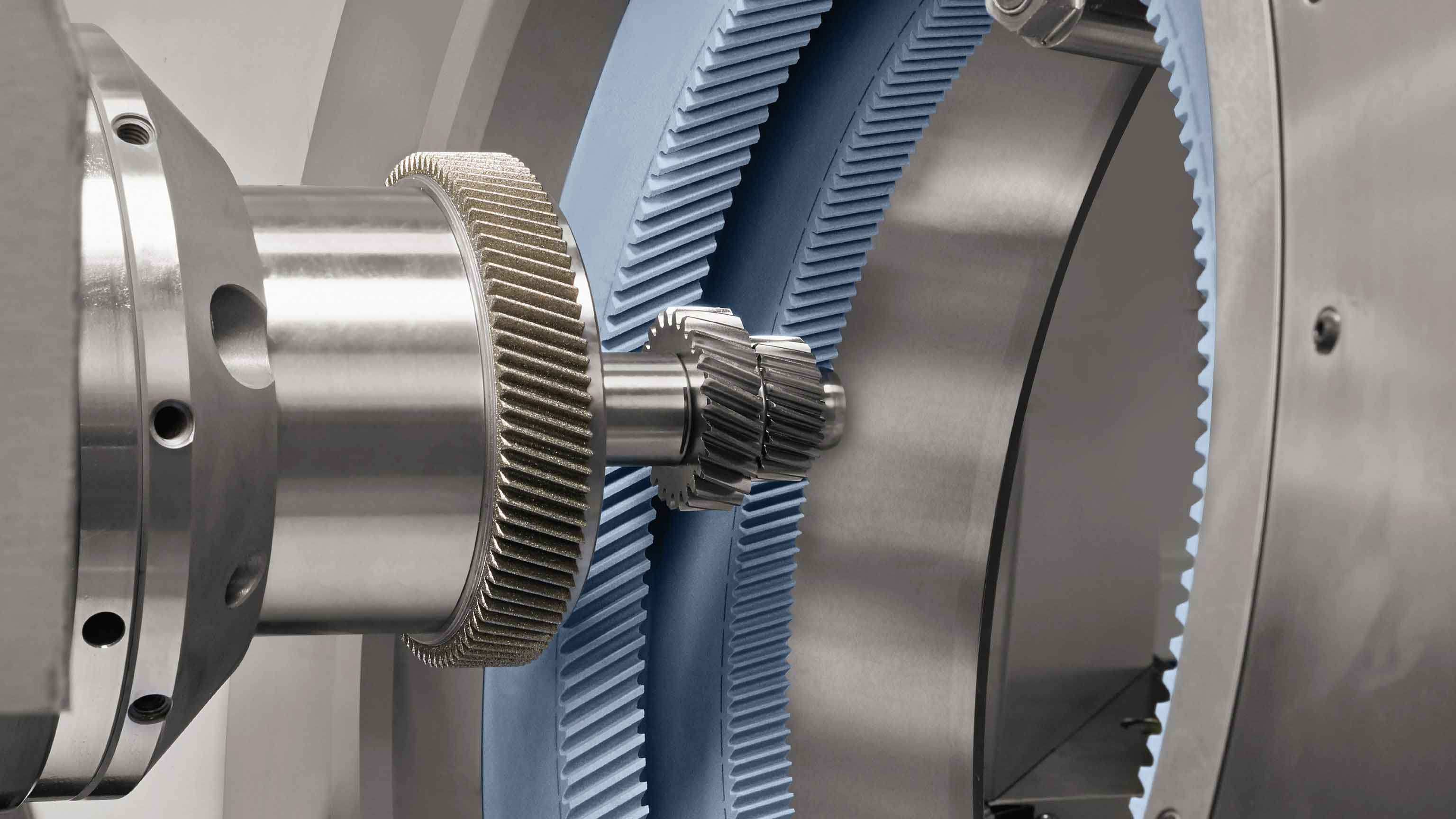
1. Principle and Application of Power Honing
Power honing is widely used in the automotive manufacturing industry. The MQ and DQ series transmissions of the Volkswagen Group commonly employ a transmission form where honed gears and ground gears mesh with each other for high-speed gears. The processing principle of power honing involves internal gear engagement with staggered axes. The cutting tool, a grinding wheel, and the gear part not only have radial cutting forces but also axial reciprocating linear motion. This combination of axial and radial cutting forms a complex staggered mesh-like tooth surface, which is conducive to smooth gear engagement and extended gear life.
2. Process Flow and Comparison of Process Differences
The process flow for the 5th-speed shift gear of the MQ250 transmission. The tooth surface processing involves gear hobbing, chamfering, heat treatment, and gear honing. The process flow for the 5th-speed shift gear of the MQ200 transmission, with a similar tooth surface processing form to MQ250. However, there are two key differences in their processes:
- MQ200 employs an integrated gear hobbing and chamfering technology, involving rough hobbing, chamfering, and then finish hobbing. This eliminates high points formed by material accumulation during chamfering on the gear tooth surface and offers high processing efficiency. MQ250 uses separate processes for gear hobbing and chamfering, characterized by independent equipment with easy size adjustment and maintenance but lower processing efficiency. Chamfering inevitably leaves burr high points on the tooth surface, affecting subsequent gear honing.
- MQ200 uses welding before heat treatment, while MQ250 uses welding after heat treatment. Welding aims to combine the gear hub (meshing gear) and the gear ring (gear cap for synchronization). Welding before heat treatment is cost-effective but the gear ring has no subsequent processing, greatly affected by heat treatment deformation. The process after heat treatment welding includes an additional “hard turning” step, where the mating surface of the gear hub and gear ring is turned to meet precision requirements. This ensures high mating precision between the gear ring and hub, unaffected by heat treatment deformation, but adds cost. Another main difference is that post-honing welding in MQ250 means honing is unaffected by the gear ring size. If the outer diameter of the gear ring is larger than the gear, the amplitude of the grinding wheel’s axial reciprocating motion is limited in gear honing process of MQ200 transmissions (small axial intersection angle), potentially causing interference with the gear ring, resulting in higher failure rates in MQ200 transmissions.
3. Common Defects in Batch Production of Power Honing
Honing is the finishing process for automotive gears and the final processing step for the tooth surface. Gear honing has high requirements for the dimensions of pre-honing blanks. Therefore, a pre-inspection system is used before processing, where the pre-inspection wheel and gear perform double-flank rolling tests to judge the machining allowance, eccentric diameter runout, and whether burr high points are within the allowed range. Compared to other finishing methods like gear grinding and shaving, honing defects are more prevalent in batch production, mainly manifesting as pre-inspection failures,砂轮打刀, dark patches on gear teeth (partially unprocessed areas on gear teeth), unqualified precision measurement reports, and unqualified online measurement dimensions, as shown in Table 1.
Table 1: Common Defects, Causes, and Proportions in Power Honing
| Defect Form | Causes | Proportion |
|---|---|---|
| Pre-inspection Failure | Mainly due to high points on gear teeth; large runout due to heat treatment deformation; insufficient or excessive machining allowance | MQ250: 30% before improvement, 1% after; MQ200: 0.2% |
| Sandwheel Breakage | Excessive cutting forces during processing (large allowance, hard spots inside parts, etc.); equipment precision issues; tool (grinding wheel/dressing wheel) problems | MQ250: 30 grinding wheels/year |
| Dark Patches on Teeth | Insufficient machining allowance; equipment precision issues (e.g., tooth sensor problems); uneven heat treatment deformation | ~0.1% |
| Size Non-conformity | Equipment precision issues; tool (grinding wheel/dressing wheel) problems; uneven heat treatment deformation | ~0.1% |
4. Two Process Improvement Methods to Address Honing Defects in Batch Production
Based on Table 1, the primary defect of MQ250 transmission before process improvement was pre-inspection failure, with a nearly 30% failure rate. The main cause of pre-inspection failure was burr high points on the gear teeth, mainly due to high points formed inevitably on the gear tooth and end surfaces during chamfering pressing. High points on the end surface can be removed using a deburring tool, but those on the tooth surface cannot. Typically, pre-inspection failures are resolved through rework, where operators use specialized hand files for obvious high points and gradually widen the pre-inspection range for less obvious ones, eventually passing unqualified parts (concession). This approach easily leads to sandwheel breakage.
Method 1 focuses on solving pre-inspection failures. The conventional process is modified to include gear hobbing, chamfering, auxiliary removal of burr high points using a shaving machine, heat treatment, and gear honing. Using the shaving machine to remove burr high points is not true shaving but lightly scraping the edges of the tooth surface with the shaving machine to remove burrs. The precision measurement report of a part after gear hobbing and chamfering (extracting the tooth lead line section), showing obvious burr high points on both ends of the tooth surface (measurement results of about 0.02mm). The measurement result of the same part after using the shaving machine to remove burr high points. By comparison, the burr high points on the tooth edge have been completely removed. The part in the left report fails the pre-inspection of gear honing machine, showing a “high points on tooth surface” alarm, while the part in the right report passes the pre-inspection smoothly, demonstrating the effectiveness of using the shaving machine to remove burr high points. Adopting this method reduced the pre-inspection failure rate of MQ250 transmissions from 30% before process improvement to 1%, significantly addressing pre-inspection failures in batch production.
In addition to affecting pre-inspection failures, burr high points on the tooth surface also significantly impact gear honing quality. The trend of abnormal wear on the grinding wheel caused by pre-honing blanks with burr high points. The experimental conditions include a Praewema honing machine, a grinding wheel dressing cycle of 85 pieces/cycle, processing gears with burr defects (burr height of about 0.02~0.05mm), and using a Discom transmission noise test bench. It can be seen that when processing the first part, there is some abnormality on the edge of the tooth lead line, but this abnormality is acceptable and does not significantly affect transmission noise. From the 20th part, the abnormal points on the tooth lead line gradually increase, and by the 40th part, the part is no longer usable, with noise exceeding specifications on the Discom transmission test bench.