
Abstract:
The method for gear hobbing pre-modification and honing allowance control oriented for hobbing-honing synergy. By establishing mathematical models for both hobbing and honing processes, analyzing the influence of various machine axes on the modified tooth surface, and proposing a novel approach for pre-modification and allowance control, this research aims to enhance the efficiency and accuracy of gear manufacturing. The findings are verified through virtual simulation, demonstrating the feasibility and effectiveness of the proposed method.
Keywords: gear hobbing, gear honing, pre-modification, allowance control, synergy, mathematical model, virtual simulation.
1. Introduction
Gears are crucial components in mechanical transmission systems, and their quality directly affects the performance and reliability of the entire system. The manufacturing process of gears involves multiple stages, among which hobbing and honing are two key processes. Hobbing, as a roughing and semi-finishing process, can efficiently produce gears with a certain degree of accuracy. Honing, on the other hand, is a finishing process that further improves the surface quality and accuracy of the gears. The synergy between hobbing and honing is crucial for achieving efficient and precise gear manufacturing.
However, the current research on the synergy between hobbing and honing processes, particularly regarding the allocation of machining allowances and the improvement of processing efficiency and accuracy, is relatively scarce. To address this issue, this paper proposes a method for gear hobbing pre-modification and honing allowance control oriented for hobbing-honing synergy.
2. Mathematical Modeling of Gear Hobbing and Honing Processes
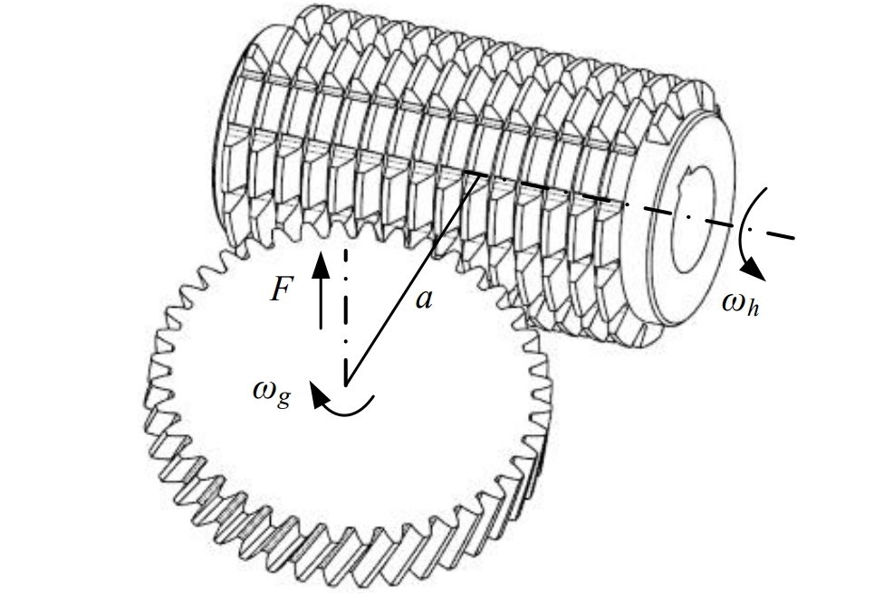
2.1 Kinematics and Mathematical Model of Hobbing Process
The kinematics of the hobbing process and the mathematical model of the hob are established based on the principles of gear manufacturing. The hob is modeled as a helical worm, and the tooth surface of the gear is obtained through the enveloping method. The parameter equation of the formed tooth surface is derived to facilitate subsequent calculations and analyses.
Table 1: Key Parameters of Hobbing Process
| Parameter | Description |
|---|---|
| φh | Angular position of the hob |
| ζ | Axial position of the hob |
| Y | Radial feed axis of the machine |
| B | Rotation axis of the hob disk |
2.2 Kinematics and Mathematical Model of Honing Process
Similarly, the kinematics of the honing process and the mathematical model of the honing wheel are established. The honing wheel is modeled based on the basic rack mathematical model, and the parameter equation of the formed tooth surface is derived through gear meshing principles.
Table 2: Key Parameters of Honing Process
| Parameter | Description |
|---|---|
| θ | Angular position of the workpiece |
| φ | Angular position of the honing wheel |
| Z | Axial position of the workpiece |
| R | Radius of the honing wheel |
3. Method for Gear Hobbing Pre-modification Based on Multi-axis Synchronization
3.1 Basic Principles of Gear Modification
Gear modification techniques, including tooth profile modification, tooth trace modification, and topological modification, are analyzed to determine the target modified tooth surface. These techniques are essential for improving the contact state and meshing performance of gear pairs.
3.2 Geometric Structure Model and Kinematics of Hobbing Machine
The geometric structure model and kinematics of the hobbing machine are established based on the principles of gear hobbing. The machine’s radial feed axis (Y-axis) and hob disk rotation axis (B-axis) are controlled in a synchronized manner to achieve the desired pre-modification.
3.3 Mathematical Model for Hobbing Pre-modification
A second-order polynomial function is used to represent the synchronized motion of the Y-axis and B-axis. Combined with the calculation of the hobbing formed tooth surface, a mathematical model for the normal machining allowance of the topologically modified tooth surface is established. A sensitivity matrix is also constructed to analyze the influence of polynomial coefficients on the normal machining allowance.
Table 3: Sensitivity Matrix for Hobbing Pre-modification
| Coefficient | Sensitivity Coefficient |
|---|---|
| a0 | S0 |
| a1 | S1 |
| a2 | S2 |
4. Synergy of Hobbing and Honing Processes and Control of Honing Allowance
4.1 Determination of Normal Machining Allowance for Honing
The normal machining allowance for honing is determined by calculating the normal deviation between the hobbing formed tooth surface and the honing formed tooth surface. This allows for the precise control of the honing allowance and ensures uniform material removal during the honing process.
4.2 Optimization of Modification Parameters
Based on the previously established mathematical models and sensitivity matrix, the modification parameters are solved and optimized using dynamic programming algorithms. This ensures that the pre-modification of the hobbing process meets the requirements for subsequent honing processes.
5. Virtual Simulation of Gear Hobbing Pre-modification Process
5.1 Setup of Virtual Machine Tool in VERICUT
The geometric structure of the hobbing machine is analyzed, and a three-dimensional model of the machine is created using UG modeling software. The machine components are individually named and saved as .prt files. In VERICUT software, the virtual hobbing machine tool is configured based on the motion characteristics, mating relationships, and positional relationships of the components.
5.2 Hob Modeling and Tool Library Configuration
The hob is parameterized and modeled using Mathematica mathematical software and UG modeling software. The hob model is then imported into the VERICUT tool library. The clamping point and tool setting point are configured to ensure accurate positioning and operation during the simulation process.
5.3 Control System, Coordinate System, and Offset Settings
The control system, coordinate system, and offsets are set up to ensure consistency between the virtual processing environment and the actual processing environment. Various common control systems, such as Fanuc, Siemens, and Cincinnati, can be simulated in VERICUT software.
5.4 NC Programming and Simulation Results Analysis
The NC program for the hobbing pre-modification process is written based on the kinematic relationships of the hobbing machine. The simulation process is run in VERICUT software, and the simulation results are analyzed to verify the feasibility and correctness of the proposed method.
Table 4: Simulation Results Analysis
| Parameter | Value |
|---|---|
| Maximum Deviation | 0.05596 mm |
| Minimum Deviation | 0.00187 mm |
| Average Deviation | – |
6. Conclusion
This paper presents a comprehensive study on gear hobbing pre-modification and honing allowance control oriented for hobbing-honing synergy. By establishing mathematical models for both hobbing and honing processes, analyzing the influence of various machine axes on the modified tooth surface, and proposing a novel approach for pre-modification and allowance control, this research has achieved significant results. The findings are verified through virtual simulation, demonstrating the feasibility and effectiveness of the proposed method.
However, further research is needed to improve and refine the proposed method. Future work will focus on optimizing the modification parameters, improving the accuracy of the mathematical models, and exploring more efficient and precise gear manufacturing processes.