
Abstract
The accurate extraction of modal parameters for the digital twin of a spiral bevel gear. Modal testing of the spiral bevel gear was conducted to obtain free-free modal frequencies, modal shapes, and frequency response functions (FRFs). The auto modal assurance criterion (Auto MAC) matrix was calculated, revealing low correlation among various modal orders, which indicates the high accuracy of the modal shapes extracted from the modal test. Based on the experimental modal frequencies, the physical properties of the spiral bevel gear were refined, and modal simulations were performed to obtain the modal frequencies, modal shapes, and FRFs in the free-free state. When compared to the modal test results, the maximum modal frequency deviation was found to be 1.235%. The cross modal assurance criterion (Cross MAC) matrix between the experimental and digital twin modal shapes was calculated, showing good consistency between them. Furthermore, the comparison of experimental and simulated FRFs further validated the accuracy of the modal analysis of the digital twin. This research demonstrates that the proposed method can solve the problems of incomplete and inaccurate measurements due to experimental constraints.
1. Introduction
Modal analysis is a fundamental means of studying structural dynamics. By determining the dynamic properties of gears, modal analysis allows for more accurate predictions of the actual operating state and performance of spiral bevel gears. Moreover, modal analysis results can guide the redesign of gears, helping designers identify structurally weak areas, modify structural dynamics, and assess changes in dynamic characteristics due to structural alterations.
Table 1. Basic parameters of the large spiral bevel gear
| Parameter | Value |
|---|---|
| Number of teeth | 33 |
| Module | 8.4848 |
| Rotation direction | Right-hand |
| Tooth width (mm) | 46 |
| Pressure angle (°) | 20 |
| Helix angle (°) | 35 |
| Pitch cone angle (°) | 51.767 |
| Face cone angle (°) | 54.193 |
| Root cone angle (°) | 48.585 |
| Midpoint cone distance (mm) | 155.23 |
| Addendum height (mm) | 5.939 |
| Dedendum height (mm) | 9.955 |
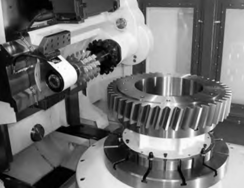
(Images of gear detection and modal testing setups can be inserted here)
2. Modal Testing of Spiral Bevel Gear
2.1 Modal Test Scheme
Modal testing was conducted on the large gear of a spiral bevel gear pair. To establish an accurate geometric model, the gear tooth surface coordinates were detected using a gear measuring center.
During the free-free modal test, the gear was suspended using 2-meter elastic nylon ropes to simulate a free boundary condition. The mobile force hammer method was adopted to test the modal parameters and modal shapes of the large gear. Incentive points and response points were evenly arranged on the back of the gear, with four acceleration sensors installed at specified measuring points. A total of 132 measuring points were planned, and each point was struck three times to obtain an average value.
2.2 Experimental Modal Analysis
Signals from the force hammer and vibration responses were collected using a signal acquisition instrument. Through the test, modal frequencies and modal shapes in the free-free state were obtained.
Table 2. Experimental modal frequencies and damping ratios of the large gear
| Modal order | Frequency (Hz) | Damping ratio (%) |
|---|---|---|
| 1 | 1436.3 | 0.098 |
| 2 | 1441.1 | 0.083 |
| … | … | … |
| 15 | 8653.2 | 0.140 |
| 16 | 8686.5 | 0.101 |
(Modal shapes images can be inserted here)
The Modal Assurance Criterion (MAC) was used to evaluate the geometric correlation between different modal shape vectors. The MAC matrix for the experimental modal shapes showed low correlation among various modal orders, proving the accuracy of the modal shapes extracted from the modal test.
3. Correction of Physical Properties and Modal Simulation
Based on the experimental results, the physical properties of the spiral bevel gear’s digital twin, such as elastic modulus, density, and Poisson’s ratio, were refined to establish a more accurate digital twin model.
3.1 Boundary Conditions for Modal Simulation
A precise finite element model of the large gear was developed based on its basic and manufacturing parameters. To simulate the experimental boundary conditions more accurately, 0-dimensional spring elements (e.g., CBUSH) combined with 1-dimensional connection elements (e.g., RBE3) were used to simulate the suspension by nylon ropes. Modal simulations were then performed to calculate the modal frequencies.
3.2 Physical Property Correction
Using the response surface methodology and a “three-factor, five-level” central composite experimental design, the elastic modulus (E), Poisson’s ratio (μ), and density (ρ) were optimized to minimize the absolute difference between the simulated and experimental modal frequencies.
Table 3. Comparison of experimental and simulated modal frequencies
| Modal order | Experimental frequency (Hz) | Simulated frequency (Hz) | Relative error (%) |
|---|---|---|---|
| 1 | 1436.3 | 1441.8 | 0.383 |
| 2 | 1441.1 | 1441.8 | 0.049 |
| … | … | … | … |
| 15 | 8653.1 | 8760.0 | 1.235 |
| 16 | 8686.5 | 8756.4 | 0.85 |
3.3 Modal Shape and FRF Analysis
Simulated modal shapes were compared with experimental ones, showing excellent agreement. The Cross MAC matrix was calculated to evaluate the consistency between experimental and simulated modal shapes, revealing high correlation along the diagonal and low correlation off-diagonal, which confirms the accuracy of the digital twin model.
FRF analysis was also conducted. Both experimental and simulated FRFs exhibited good peak alignment with modal frequencies. Simulated FRFs revealed modal frequencies that were difficult to identify experimentally, demonstrating the digital twin’s ability to discern modal parameters beyond experimental limitations.
4. Conclusion
In this study, modal testing of a spiral bevel gear was performed to obtain modal parameters. Based on experimental modal frequencies, the physical properties of the spiral bevel gear were refined, and a digital twin model was developed. Comparisons between simulation and experimental results validated the accuracy of the digital twin.