Introduction:
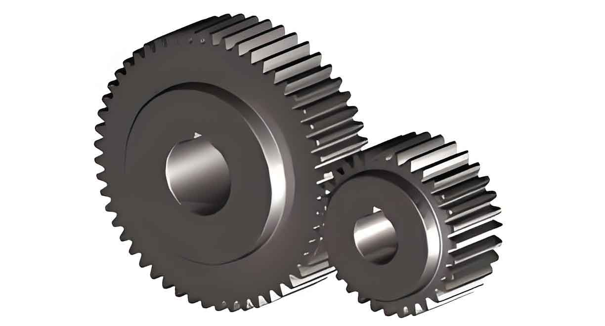
Spur gears are widely used in mechanical systems due to their high transmission efficiency, long lifespan, and stable gear ratio. The performance of the gear depends significantly on the contact stress during meshing. If this stress exceeds certain thresholds, it can lead to issues such as wear, pitting, and failure. Therefore, accurate calculation of contact stresses, especially the maximum contact stress, is essential in gear design.

Contact Stress Calculation Using Hertzian Formula:
The contact stress between two meshing teeth is calculated using the Hertzian theory, where the contact stress σH\sigma_HσH is derived based on factors such as the normal force, the tooth radius, and the material properties (modulus of elasticity and Poisson’s ratio). The formula involves the relative curvature at the contact point and the elastic coefficients of the gears.
For a pair of meshing gears, the Hertzian contact stress σH\sigma_HσH at any contact point iii can be expressed as:σH=KFnπb(1ρ1+1ρ2)(1−ν12E1+1−ν22E2)\sigma_H = \frac{K F_n}{\pi b \left(\frac{1}{\rho_1} + \frac{1}{\rho_2}\right)} \left( \frac{1 – \nu_1^2}{E_1} + \frac{1 – \nu_2^2}{E_2} \right)σH=πb(ρ11+ρ21)KFn(E11−ν12+E21−ν22)
Where:
- KKK is the load correction factor.
- FnF_nFn is the normal force between the teeth.
- ρ1,ρ2\rho_1, \rho_2ρ1,ρ2 are the radii of curvature at the contact points.
- E1,E2E_1, E_2E1,E2 are the elastic moduli.
- ν1,ν2\nu_1, \nu_2ν1,ν2 are the Poisson’s ratios of the materials.
Maximum Contact Stress and Node Contact Stress Ratio:
The maximum contact stress σHmax\sigma_{Hmax}σHmax is a critical value in gear design because it determines the durability of the gear teeth under load. The ratio between the maximum contact stress and the node contact stress (the stress at the node of meshing teeth) is referred to as the “stress ratio” λ\lambdaλ.
The stress ratio λ\lambdaλ is influenced by:
- The number of teeth on the small gear (Z1Z_1Z1).
- The transmission ratio (uuu).
For example, when the number of teeth on the small gear Z1Z_1Z1 exceeds 17, the stress ratio decreases as Z1Z_1Z1 increases. However, if Z1Z_1Z1 is less than 17, the stress ratio increases as Z1Z_1Z1 grows. This implies that the maximum contact stress becomes critical when Z1Z_1Z1 is near 17.
Stress Ratio Analysis and Design Criteria:
The stress ratio’s dependence on the gear design parameters, such as Z1Z_1Z1 and uuu, can significantly affect the need for precise contact fatigue strength calculations. The study shows that for gear designs with a stress ratio greater than or equal to 8%, it is necessary to perform detailed calculations for the maximum contact stress.
Tables and Graphs:
The article uses several graphs and tables to illustrate how the stress ratio varies with different parameters such as the number of teeth and transmission ratio. For example, when Z1Z_1Z1 is between 10 and 17, the stress ratio increases, highlighting the importance of precise gear design calculations when these values are reached.
Conclusion:
The research provides valuable insights into the design and analysis of involute spur gears, emphasizing the importance of calculating the maximum contact stress accurately. The derived formulas and stress ratio analysis help engineers optimize gear performance, reducing wear and enhancing reliability.
This document offers a solid framework for gear designers, particularly those working on systems requiring high-efficiency transmission with optimal durability. The detailed formulas and approach to calculating contact stresses and stress ratios are essential for improving the precision of gear transmissions and minimizing failure risks due to excessive stress.
