1. Introduction
The spur gear transmission system, widely utilized in mechanical equipment due to its compact structure, high efficiency, and constant transmission ratio, is a cornerstone of modern machinery. However, nonlinear phenomena such as bifurcation, tooth surface impact, and disengagement significantly affect system stability, fatigue life, and reliability. This study investigates the nonlinear dynamic characteristics of spur gear systems, focusing on bifurcation mechanisms, tooth surface impact dynamics, and parameter matching laws under multi-frequency excitations.

1.1 Background and Significance
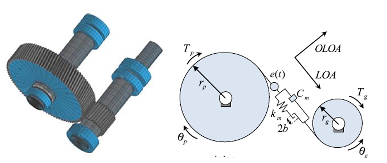
Spur gears are fundamental components in industries ranging from wind turbines to automotive transmissions. Despite their advantages, inherent nonlinearities—such as time-varying mesh stiffness, backlash, and static transmission errors—induce complex dynamic behaviors, including chaos, amplitude jumps, and multi-periodic motions. Understanding these dynamics is critical for optimizing design parameters, reducing vibration/noise, and enhancing operational lifespan.
1.2 Research Objectives
- Establish nonlinear dynamic models for spur gear pairs, single-stage, and multi-stage hybrid gear systems.
- Analyze bifurcation patterns, tooth surface impact characteristics, and stability under parameter variations.
- Develop improved algorithms (e.g., CPNF, harmonic balance) for tracking periodic motions and controlling chaos.
2. Theoretical Foundations
2.1 Nonlinear Bifurcation Theory
The dynamics of spur gear systems are governed by nonlinear differential equations. Key concepts include:
- Poincaré Mapping: Transforms continuous dynamics into discrete systems for stability analysis.
- Floquet Multipliers: Determine the stability of periodic solutions. A multiplier exceeding 1 indicates bifurcation.
- Lyapunov Exponents: Quantify trajectory divergence, distinguishing chaotic (λ>0λ>0) from periodic (λ≤0λ≤0) regimes.
2.2 Key Metrics for Dynamic Analysis
- Tooth Surface Impact (TSI): Classified as no-impact (TSI=0TSI=0), single-side impact (TSI=1TSI=1), or double-side impact (TSI=2TSI=2).
- Disengagement Duty Cycle (DC1): Ratio of disengagement time to total cycle time.
- Dynamic Load Coefficient (DLC): DLC=FmaxdynamicFmeanDLC=FmeanFmaxdynamic, reflecting load fluctuations.
2.3 Improved CPNF Algorithm
The Continuous-Poincaré Newton-Floquet (CPNF) method tracks periodic solutions in piecewise-smooth systems. Key steps include:
- Initialization: Define Poincaré sections and Jacobian matrices.
- Newton Iteration: Solve for fixed points using finite-difference approximations at non-smooth boundaries.
- Bifurcation Tracking: Use parameter continuation to trace stability boundaries.
3. Single-Degree-of-Freedom (SDOF) Spur Gear Pair Dynamics
3.1 Nonlinear Dynamic Model
The dimensionless torsional vibration equation for a spur gear pair is:x¨+2ξx˙+km(τ)f(x,b)=fm+fahΩ2sin(Ωτ+ϕ1),x¨+2ξx˙+km(τ)f(x,b)=fm+fahΩ2sin(Ωτ+ϕ1),
where f(x,b)f(x,b) is the backlash function, km(τ)km(τ) is time-varying stiffness, and ξξ is damping ratio.
3.2 Bifurcation and Impact Characteristics
- Parameter Sensitivity: Bifurcation diagrams in (Ω,α)(Ω,α)-plane reveal transitions from periodic to chaotic motions (Fig. 1).
- Impact States: At Ω=1.7Ω=1.7, chaotic regions expand with increasing backlash bb, while soft tooth surfaces (α<0.2α<0.2) exhibit stronger nonlinearity.
Table 1: Impact of Backlash on Bifurcation
| Backlash (bb) | Dominant Motion | Chaos Region |
|---|---|---|
| 0.1 | 1/1, 2/1 | Moderate |
| 0.5 | 1/1 | Large |
| 1.0 | 1/1 | Small |
3.3 Stability Analysis
- Basin of Attraction: Initial conditions near x=±bx=±b lead to multi-periodic or chaotic attractors.
- Vibration Intensity Stability: Defined by thresholds x∗x∗, regions with xmax>x∗xmax>x∗ are unstable.
4. Three-Degree-of-Freedom (3-DOF) Spur Gear System
4.1 Dynamic Model with Bearing Clearance
The 3-DOF model incorporates bearing support stiffness kbikbi, damping cbicbi, and radial clearance bibi:{mg1y¨g1+cb1y˙g1+kb1f(yg1,b1)=−Fb1,mg2y¨g2+cb2y˙g2+kb2f(yg2,b2)=−Fb2,mex¨+chx˙+kh(t)f(x,bh)=Fm.⎩⎨⎧mg1y¨g1+cb1y˙g1+kb1f(yg1,b1)=−Fb1,mg2y¨g2+cb2y˙g2+kb2f(yg2,b2)=−Fb2,mex¨+chx˙+kh(t)f(x,bh)=Fm.
4.2 Bifurcation and Chaos Control
- Period-Doubling Bifurcation: At Ω=1.44Ω=1.44, Floquet multipliers ∣λ∣>1∣λ∣>1 trigger chaos (Fig. 2).
- OGY Chaos Control: Stabilizes unstable periodic orbits (UPOs) by perturbing system parameters.
Table 2: Stability of Periodic Orbits
| Frequency (ΩΩ) | Coexisting Orbits | Stability |
|---|---|---|
| 1.54–1.528 | P1 | Stable |
| 1.527–1.505 | P1, P2 | P2 stable |
| 1.504–1.444 | P1, P2, P4 | P4 stable |
| 1.443–1.420 | P1, P2, P4, P8 | P8 stable |
5. Multi-Stage Hybrid Gear System Dynamics
5.1 Nonlinear Model with Multi-Frequency Excitation
A hybrid system combining planetary and parallel-axis gears introduces multi-mesh frequencies Ωj=ΛjΩΩj=ΛjΩ. The dimensionless equation is:x¨j+2ξjx˙j+kj(t)f(xj,bj)=Fmj+∑r=1∞Fahrsin(rΩτ+ϕr).x¨j+2ξjx˙j+kj(t)f(xj,bj)=Fmj+r=1∑∞Fahrsin(rΩτ+ϕr).
5.2 Asynchronous Bifurcation
- Parameter Mismatch: Variations in backlash bb, stiffness kk, and damping ξξ cause non-synchronous bifurcation across gear stages.
- Shaft Torsional Stiffness: Lower stiffness suppresses front-stage nonlinearities but amplifies rear-stage vibrations.
Table 3: Dynamic Characteristics of Hybrid Systems
| Parameter | Planetary Gear | Fixed-Axis Gear | Shaft Response |
|---|---|---|---|
| Amplitude Jump | Strong | Weak | Nonlinear |
| Frequency Response | Multi-peak | Single-peak | Linear |
6. Influence of Tooth Surface Flash Temperature
6.1 Thermal-Deformation Coupled Model
Based on H.Blok and Hertz theories, flash temperature ΔT(t)ΔT(t) alters backlash bb and mesh stiffness km(t)km(t):ΔT(t)=μfm(t)∣v1−v2∣(λ1ρ1c1v1+λ2ρ2c2v2)B(t).ΔT(t)=(λ1ρ1c1v1+λ2ρ2c2v2)B(t)μfm(t)∣v1−v2∣.
6.2 Thermal Effects on Dynamics
- Stiffness Reduction: km(t)km(t) decreases by 10–20% at ΔT>50∘CΔT>50∘C.
- Bifurcation Shift: Higher ΔTΔT expands chaotic regions in (Ω,ΔT)(Ω,ΔT)-plane (Fig. 3).
Table 4: Impact of Flash Temperature
| ΔTΔT (°C) | DLCDLC | DC1DC1 | Stability |
|---|---|---|---|
| 0 | 1.5–2.0 | 0.1–0.3 | Stable |
| 30 | 2.0–3.0 | 0.3–0.5 | Moderate |
| 60 | 3.0–5.0 | 0.5–0.7 | Unstable |
7. Conclusions
- Parameter Matching: Optimal backlash (b=0.5–1.0b=0.5–1.0) and damping (ξ=0.05–0.1ξ=0.05–0.1) minimize bifurcation and tooth surface impact.
- Chaos Control: Improved OGY algorithm effectively stabilizes high-dimensional spur gear systems.
- Thermal Management: Reducing flash temperature (ΔT<30∘CΔT<30∘C) enhances stability and load capacity.
This study provides a theoretical foundation for spur gear design, emphasizing the interplay between nonlinear dynamics and operational parameters. Future work will explore real-time monitoring and adaptive control strategies for industrial applications.
Key Formulas
- Nonlinear Backlash Function:
f(x,b)={x−b,x>b,0,∣x∣≤b,x+b,x<−b.f(x,b)=⎩⎨⎧x−b,0,x+b,x>b,∣x∣≤b,x<−b.
- Dynamic Load Coefficient:
DLC=max(∣km(τ)f(x,b)+ξx˙∣)Fm.DLC=Fmmax(∣km(τ)f(x,b)+ξx˙∣).
- Flash Temperature:
ΔT(t)∝μfm∣v1−v2∣B(t).ΔT(t)∝B(t)μfm∣v1−v2∣.
