Abstract
As critical components in mechanical transmission systems, spur gear is widely recognized for their high transmission efficiency, precise speed ratios, and power-handling capabilities. However, under complex operational conditions, spur gear is prone to fatigue fractures at the tooth root due to cyclic bending stresses. Accurately calculating these stresses is essential for optimizing gear design and extending service life. Traditional methods, such as the Lewis formula and finite element analysis (FEA), face limitations in geometric accuracy and computational efficiency. This study proposes an isogeometric analysis (IGA) framework using Non-Uniform Rational B-Splines (NURBS) to evaluate the bending strength of spur gear. By comparing results from the Lewis formula, FEA, and IGA, we demonstrate that IGA offers superior precision, smoother stress distributions, and reduced computational time. This work lays the foundation for applying IGA to complex three-dimensional gear models and contact analyses in future research.

1. Introduction
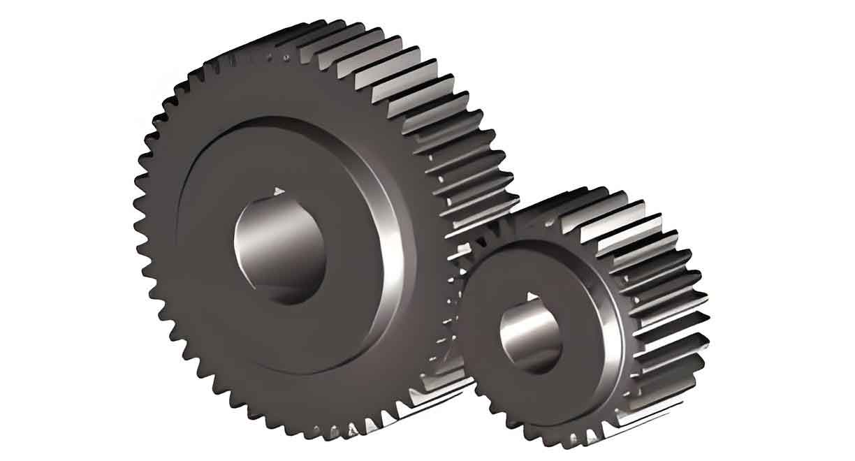
Spur gear is fundamental elements in mechanical systems, transmitting torque and motion between parallel shafts. Their performance directly impacts the reliability and efficiency of machinery. However, the tooth root region of spur gear is susceptible to bending fatigue under cyclic loads, leading to crack initiation and catastrophic failure. Accurate prediction of bending stresses is critical for designing durable gears.
Traditional approaches, such as the Lewis formula, simplify gear teeth as cantilever beams but neglect geometric complexities. Meanwhile, FEA struggles with mesh generation inefficiencies and geometric discretization errors. To address these challenges, this study leverages isogeometric analysis (IGA), which integrates Computer-Aided Design (CAD) geometries with NURBS-based approximations. By eliminating mesh generation and enhancing geometric fidelity, IGA provides a robust framework for analyzing spur gear bending strength.
2. Literature Review
2.1 Traditional Methods for Spur Gear Bending Strength
The Lewis formula, introduced in 1892, calculates bending stress by modeling the gear tooth as a parabolic cantilever beam. The simplified equation is:σF=KFtbmYFaYSaσF=bmKFtYFaYSa
where FtFt is the tangential load, bb is the face width, mm is the module, and YFaYFa, YSaYSa are correction factors. While foundational, this method oversimplifies stress distributions and ignores geometric nuances.
Subsequent studies improved accuracy by incorporating dynamic load factors, finite element simulations, and neural networks. For example, Filiz and Eyercioglu [4] simulated contact stresses using FEA, while Gao [6] employed BP neural networks to predict fatigue limits. Despite advancements, these methods still rely on coarse geometric approximations.
2.2 Isogeometric Analysis (IGA)
IGA, proposed by Hughes et al. [1], unifies CAD and FEA by using NURBS basis functions for both geometric modeling and numerical analysis. Key advantages include:
- Geometric Exactness: NURBS precisely represent complex curves and surfaces.
- Higher Continuity: C1C1-continuous basis functions yield smoother stress fields compared to FEA’s C0C0 elements.
- Efficiency: Eliminates time-consuming mesh generation.
IGA has been applied to shells [8], fracture mechanics [9], and fluid-structure interaction [10]. However, its application to spur gear remains limited.
3. Methodology
3.1 NURBS-Based Modeling of Spur Gear
NURBS surfaces are defined by control points, weights, and knot vectors. For a 2D spur gear model, the NURBS surface S(ξ,η)S(ξ,η) is expressed as:S(ξ,η)=∑i=1n∑j=1mRi,jp,q(ξ,η)Pi,jS(ξ,η)=i=1∑nj=1∑mRi,jp,q(ξ,η)Pi,jRi,jp,q(ξ,η)=Ni,p(ξ)Mj,q(η)wi,j∑k=1n∑l=1mNk,p(ξ)Ml,q(η)wk,lRi,jp,q(ξ,η)=∑k=1n∑l=1mNk,p(ξ)Ml,q(η)wk,lNi,p(ξ)Mj,q(η)wi,j
where Ni,pNi,p and Mj,qMj,q are B-spline basis functions, wi,jwi,j are weights, and Pi,jPi,j are control points.
Table 1: Geometric Parameters of the Spur Gear Model
| Parameter | Symbol | Value | Unit |
|---|---|---|---|
| Module | mnmn | 2 | mm |
| Number of Teeth | ZZ | 30 | – |
| Face Width | bb | 15 | mm |
| Pressure Angle | αα | 20° | Degree |
| Addendum Coefficient | haha | 1 | – |
| Dedendum Coefficient | cc | 0.25 | – |
3.2 Isogeometric Analysis Workflow
The IGA workflow for spur gear bending strength analysis includes:
- Model Import: NURBS-based CAD geometry.
- Boundary Conditions: Fixed constraints at the gear center; tangential load (Ft=1064.17 kNFt=1064.17kN) applied at the tooth tip.
- Assembly: Global stiffness matrix assembly using NURBS basis functions.
- Solution: Linear static analysis in MATLAB.
Table 2: IGA Computational Steps
| Step | Description |
|---|---|
| Material Definition | Elastic modulus E=210 GPaE=210GPa, Poisson’s ratio μ=0.3μ=0.3 |
| Load Application | Uniform load split into radial and tangential components |
| Matrix Assembly | Element stiffness matrices integrated into global matrix |
| Stress Calculation | Von Mises stress distribution |
4. Results and Discussion
4.1 Comparative Analysis of Stress Values
Three methods were compared:
- Lewis Formula: σF=150.15 MPaσF=150.15MPa.
- FEA (Coarse Mesh): 137.7 MPa137.7MPa.
- FEA (Refined Mesh): 139.1 MPa139.1MPa.
- IGA: 141.3 MPa141.3MPa.
Table 3: Maximum Bending Stress Comparison
| Method | Stress (MPa) | Deviation from IGA (%) |
|---|---|---|
| Lewis Formula | 150.15 | +6.25 |
| FEA (Coarse) | 137.7 | -2.55 |
| FEA (Refined) | 139.1 | -1.55 |
| IGA | 141.3 | 0 |
IGA results align closely with refined FEA, validating its accuracy. The Lewis formula overestimates stress due to simplifications.
4.2 Computational Efficiency
Table 4: Computational Time Comparison
| Method | Meshing Time (s) | Solving Time (s) | Total Time (s) |
|---|---|---|---|
| FEA (Coarse) | 20.3 | 2.5 | 22.8 |
| FEA (Refined) | 29.9 | 4.3 | 34.2 |
| IGA | 0 | 3.4 | 3.4 |
IGA eliminates meshing, reducing total time by 85–90% compared to FEA.
4.3 Stress Field Smoothness
IGA produces smoother stress contours due to C1C1-continuous NURBS basis functions, whereas FEA exhibits jagged transitions from C0C0-continuous Lagrange elements. This advantage is critical for identifying stress concentration zones in spur gear.
5. Conclusion
This study demonstrates that isogeometric analysis is a superior alternative to traditional methods for evaluating bending strength in spur gear. Key findings include:
- Accuracy: IGA results converge toward refined FEA while avoiding geometric errors.
- Efficiency: Elimination of meshing reduces computational time by 90%.
- Smoothness: C1C1-continuous stress fields enhance post-processing clarity.
Future work will extend IGA to 3D spur gear models and dynamic contact analyses. By bridging CAD and CAE, IGA promises to revolutionize gear design workflows.
