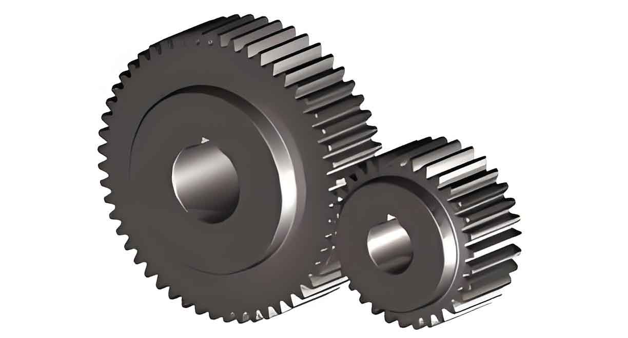
1. Fundamental Requirements of Spur Gear Transmission
Spur gear must meet two primary design criteria:
1.1 Constant Transmission Ratio
A constant instantaneous transmission ratio is vital to prevent inertial forces, vibrations, and noise. For spur gear, this is achieved using involute tooth profiles. The law of gearing states that the common normal at the contact point must intersect the line of centers at a fixed point (the pitch point). Mathematically, this ensures:i12=ω1ω2=O2PO1P=constanti12=ω2ω1=O1PO2P=constant
where O1O1 and O2O2 are the centers of the driving and driven gears, and PP is the pitch point.
1.2 Load-Carrying Capacity
The load-bearing capacity of a spur gear depends on tooth geometry, particularly the module (mm), pressure angle (αα), and number of teeth (zz). The tooth root experiences maximum bending stress, making accurate tooth thickness calculations critical for strength analysis.
2. Key Parameters of Standard Spur Gear
Understanding the nomenclature and parameters of spur gear is foundational. Below is a summary:
2.1 Geometric Definitions
- Pitch Circle: The reference circle where the module and pressure angle are standardized.
- Base Circle: The circle from which the involute profile is generated.
- Addendum Circle: The outermost circle of the gear.
- Dedendum Circle: The circle at the root of the teeth.
2.2 Primary Parameters
| Parameter | Symbol | Formula/Value |
|---|---|---|
| Module | mm | Standardized values (e.g., 1, 2, 3 mm) |
| Number of Teeth | zz | User-defined |
| Pressure Angle | αα | 20∘20∘ (standard) |
| Pitch Diameter | dd | d=m⋅zd=m⋅z |
| Base Diameter | dbdb | db=d⋅cosαdb=d⋅cosα |
| Addendum Height | haha | ha=1⋅mha=1⋅m |
| Dedendum Height | hfhf | hf=1.25⋅mhf=1.25⋅m |
3. Base Circle Tooth Thickness Derivation
The tooth thickness at the base circle (SbSb) is pivotal for calculating thickness at any arbitrary point K. Let’s derive SbSb:
3.1 Pitch Circle Tooth Thickness
At the pitch circle, tooth thickness (SS) equals the space width (ee) due to symmetry:S=πm2S=2πm
3.2 Transition to Base Circle
The base circle tooth thickness depends on the involute function (invα=tanα−αinvα=tanα−α). The derivation yields:Sb=mcosα(π2+z⋅invα)Sb=mcosα(2π+z⋅invα)
This formula links the base circle thickness to the gear’s module, pressure angle, and number of teeth.
4. Tooth Thickness at Any Point K
To compute the tooth thickness at an arbitrary point K (with radius RkRk and pressure angle αkαk), we use the following relationship:
4.1 General Formula
Sk=S⋅RkR−2Rk(invαk−invα)Sk=S⋅RRk−2Rk(invαk−invα)
where:
- SS = Pitch circle tooth thickness (πm22πm)
- RR = Pitch circle radius (R=mz2R=2mz)
- invαk=tanαk−αkinvαk=tanαk−αk
4.2 Practical Example
For a spur gear with m=3m=3, z=40z=40, and α=20∘α=20∘, calculate SkSk at Rk=70Rk=70 mm:
- Compute αkαk:
cosαk=RbRk=mzcosα2Rk=3⋅40⋅cos20∘2⋅70≈0.824cosαk=RkRb=Rk2mzcosα=2⋅703⋅40⋅cos20∘≈0.824αk=arccos(0.824)≈34.5∘αk=arccos(0.824)≈34.5∘
- Calculate invαinvα and invαkinvαk:
invα=tan20∘−20∘⋅π180≈0.0149invα=tan20∘−20∘⋅180π≈0.0149invαk=tan34.5∘−34.5∘⋅π180≈0.0836invαk=tan34.5∘−34.5∘⋅180π≈0.0836
- Substitute into SkSk:
Sk=π⋅32⋅7060−2⋅70⋅(0.0836−0.0149)≈6.93 mmSk=2π⋅3⋅6070−2⋅70⋅(0.0836−0.0149)≈6.93mm
5. Tooth Thickness at the Root Circle
The root circle tooth thickness (SfSf) is critical for bending strength analysis. Its formula is:Sf=S⋅RfR−2Rf(invαf−invα)Sf=S⋅RRf−2Rf(invαf−invα)
where Rf=m(z−2.5)2Rf=2m(z−2.5) and αf=arccos(zcosαz−2.5)αf=arccos(z−2.5zcosα).
5.1 Case Study: m=3m=3, z=45z=45
- Compute RfRf:
Rf=3(45−2.5)2=63.75 mmRf=23(45−2.5)=63.75mm
- Calculate αfαf:
cosαf=45⋅cos20∘45−2.5≈0.891⇒αf≈27∘cosαf=45−2.545⋅cos20∘≈0.891⇒αf≈27∘
- Determine SfSf:
Sf=π⋅32⋅63.7567.5−2⋅63.75⋅(inv27∘−inv20∘)≈6.31 mmSf=2π⋅3⋅67.563.75−2⋅63.75⋅(inv27∘−inv20∘)≈6.31mm
6. Comparative Analysis of Tooth Thickness
To illustrate how tooth thickness varies across different positions, consider a spur gear with m=3m=3 and α=20∘α=20∘:
| Number of Teeth (zz) | Pitch Circle (SS) | Base Circle (SbSb) | Root Circle (SfSf) | 15° Pressure Angle (S15∘S15∘) |
|---|---|---|---|---|
| 20 | 4.71 mm | 5.10 mm | 5.27 mm | 5.10 mm |
| 30 | 4.71 mm | 5.35 mm | 5.69 mm | 5.35 mm |
| 40 | 4.71 mm | 5.61 mm | 6.11 mm | 5.61 mm |
| 50 | 4.71 mm | 5.73 mm | 6.32 mm | 5.73 mm |
Key Observations:
- Pitch circle thickness (SS) remains constant for a given module.
- Base and root circle thickness increase with the number of teeth.
- Higher pressure angles reduce tooth thickness at the tip but enhance load capacity.
7. Practical Applications in Spur Gear Design
7.1 Manufacturing Considerations
- Hobbing and Shaping: Tooth thickness deviations impact meshing efficiency. Formulas ensure compliance with ISO standards.
- Quality Control: Use coordinate measuring machines (CMMs) to validate SkSk at critical points.
7.2 Fatigue and Wear Analysis
- Bending Stress: Use SfSf in the Lewis bending equation:
σb=Ftbm⋅1Yσb=bmFt⋅Y1
where YY is the Lewis form factor, dependent on tooth geometry.
- Surface Durability: Optimize SbSb to balance contact stress and pitting resistance.
8. Advanced Topics
8.1 Non-Standard Spur Gear
For gears with modified profiles (e.g., profile-shifted gears), recalculate SkSk using adjusted addendum and dedendum coefficients.
8.2 Thermal Effects
Thermal expansion alters tooth thickness. Compensate using:Sk,thermal=Sk⋅(1+αTΔT)Sk,thermal=Sk⋅(1+αTΔT)
where αTαT is the coefficient of thermal expansion.
9. Summary Tables for Quick Reference
Table 1: Key Formulas for Spur Gear Tooth Thickness
| Parameter | Formula |
|---|---|
| Pitch Circle Thickness | S=πm2S=2πm |
| Base Circle Thickness | Sb=mcosα(π2+z⋅invα)Sb=mcosα(2π+z⋅invα) |
| Arbitrary Point K Thickness | Sk=S⋅RkR−2Rk(invαk−invα)Sk=S⋅RRk−2Rk(invαk−invα) |
| Root Circle Thickness | Sf=S⋅RfR−2Rf(invαf−invα)Sf=S⋅RRf−2Rf(invαf−invα) |
Table 2: Standard Module Series (ISO)
| First Series (mm) | Second Series (mm) |
|---|---|
| 1, 1.25, 1.5, 2, 2.5, 3, 4 | 1.125, 1.375, 1.75, 2.25, 2.75, 3.5, 4.5 |
10. Conclusion
Mastering the calculation of tooth thickness at any point on a spur gear is indispensable for engineers. From ensuring smooth power transmission to preventing premature failure, these principles form the bedrock of reliable gear design. By leveraging the formulas and tables provided, designers can optimize spur gear for diverse applications, balancing strength, efficiency, and manufacturability. Whether you’re analyzing root stress or fine-tuning thermal expansions, a deep understanding of tooth geometry will always be your greatest ally.
