1. Introduction
Since the implementation of China’s manufacturing power strategy, traditional mechanical production has been transitioning to advanced automation. Industrial AI robots play a pivotal role in this transformation, where the performance of precision reducers directly affects their reliability. Currently, precision reducers heavily rely on imports, and core technologies such as manufacturing processes remain unmastered, severely restricting the development of domestic industrial robots. To address the increasing demand for industrial AI robots and existing challenges in precision reducers, this study focuses on designing a precision worm gear reducer for industrial robots.

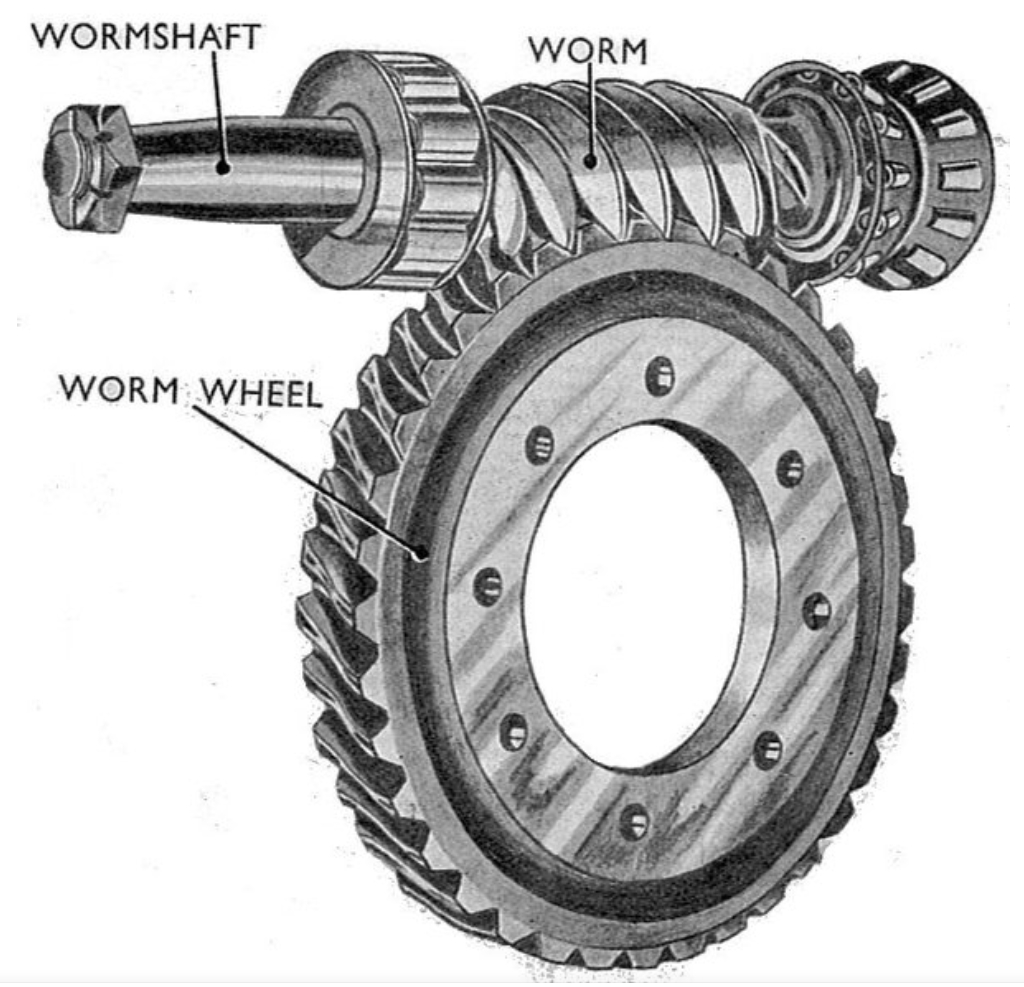
The worm gear reducer, characterized by compact structure, high torque capacity, and large transmission ratio, is ideal for AI robotic joints. However, traditional single-worm drives face issues such as low efficiency, rapid wear, and thermal losses due to sliding friction. This research proposes a three-worm drive worm gear transmission system to mitigate these challenges. By reducing relative sliding velocity and optimizing load distribution, the design aims to enhance transmission efficiency, precision, and durability.
2. Mathematical Modeling of Three-Worm Drive Worm Gear Transmission
2.1 Principles of Three-Worm Drive
The three-worm drive system employs three symmetrically arranged worms to engage with a single worm wheel. This configuration reduces dynamic load impacts, minimizes meshing gaps, and improves load-sharing performance. The kinematic relationship between the worms and the worm wheel is derived using spatial geometry and meshing principles.
2.2 Coordinate System Setup
Multiple coordinate systems are established to model the transmission:
- Static and dynamic frames for each worm (Σ1,Σ3,Σ4Σ1,Σ3,Σ4) and the worm wheel (Σ2Σ2).
- Transformation matrices for vector and coordinate conversions (Equations 2.1–2.28).
The relative angular velocity (ωsωs) and velocity vectors (vsvs) at meshing points are calculated as:ωs=ωsxi2+ωsyj2+ωszk2ωs=ωsxi2+ωsyj2+ωszk2vs=vsxis+vsyjs+vszksvs=vsxis+vsyjs+vszks
2.3 Meshing Geometry
Key equations governing worm gear meshing include:
- Meshing Function:
Φ=N1sinφ2+N2cosφ2+N5=0Φ=N1sinφ2+N2cosφ2+N5=0
- Contact Line Equations: Derived for both the worm and worm wheel surfaces.
- Lubrication Angle (μμ):
μ=sin−1(vsxωsy−vsyωsx(vsx)2+(vsy)2(ωsx)2+(ωsy)2)μ=sin−1((vsx)2+(vsy)2(ωsx)2+(ωsy)2vsxωsy−vsyωsx)
3. Structural Design and 3D Modeling
3.1 Technical Specifications
The reducer is designed for AI robotic joints with the following specifications:
| Parameter | Value |
|---|---|
| Input Speed | 1500 rpm |
| Output Torque | 1125 N·m |
| Transmission Error | ≤50 arcsec |
| Efficiency | ≥70% |
| Dimensions | 262×262×100 mm |
3.2 Gear and Worm Gear Parameter Selection
Critical parameters for gears and worm gears are summarized below:
Table 1: Gear Parameters
| Component | Module (mm) | Teeth | Pressure Angle (°) | Material |
|---|---|---|---|---|
| Input Gear | 1 | 30 | 20 | 20CrMnTi |
| Large Gear | 1 | 72 | 20 | 40Cr |
| Bevel Gear | 1.5 | 20 | 20 | 40Cr |
Table 2: Worm Gear Parameters
| Component | Module (mm) | Teeth | Lead Angle (°) | Material |
|---|---|---|---|---|
| Worm | 1.5 | 1 | 4.71 | 40Cr |
| Worm Wheel | 1.5 | 45 | – | ZCuSn10P1 |
3.3 3D Modeling
Using SolidWorks and Kisssoft, 3D models of gears, worm gears, and support structures were created. The assembly (Figure 3-3) ensures compactness and alignment for optimal load distribution.
4. Finite Element Analysis and Modal Characteristics
4.1 Strength Verification
Gear Transmission:
- Bending Stress:
σF=KFtYFaYSaYebmσF=bmKFtYFaYSaYe
- Contact Stress:
σH=ZHZEZeKFt(u+1)bd1uσH=ZHZEZebd1uKFt(u+1)
Table 3: Strength Results (Gears)
| Load Case | Theoretical (MPa) | FEA (MPa) | Safety Factor |
|---|---|---|---|
| Rated Load | 300.78 | 326.97 | 1.9 |
| Overload | 332.29 | 352.53 | 1.7 |
Worm Gear Pair:
- Maximum von Mises stress: 181.01 MPa (below material yield strength of 320 MPa).
4.2 Modal Analysis
The first six natural frequencies and mode shapes were identified:
Table 4: Modal Frequencies
| Mode | Frequency (Hz) | Deformation Characteristics |
|---|---|---|
| 1 | 4165.3 | Vertical vibration of worm shafts |
| 2 | 4174.4 | Lateral vibration of worm shafts |
| 3 | 4179.8 | Lateral vibration of worm wheel |
| 4 | 4469.1 | Vertical vibration of worm wheel |
| 5 | 4476.7 | Torsional vibration of worm shafts |
| 6 | 4481.0 | Torsional vibration of gears |
No resonance risks were detected, as operational frequencies (≤2570 Hz) were far below the lowest natural frequency.
5. Kinematic Analysis Using ADAMS
5.1 Virtual Prototyping
A multi-body dynamics model was built to simulate angular velocity profiles and transmission errors. Key steps included:
- Importing and simplifying the 3D model.
- Defining constraints, contacts, and STEP-driven inputs.
5.2 Simulation Results
Table 5: Angular Velocity Comparison
| Component | Theoretical (rpm) | Simulated (rpm) | Error (%) |
|---|---|---|---|
| Input Shaft | 1404 | 1404 | 0 |
| Large Gear | 585 | 584.36 | 0.11 |
| Worm Shaft | 585 | 583.59 | 0.24 |
| Worm Wheel | 13 | 12.92 | 0.59 |
Transmission Error Spectrum:
- Dominant frequencies at 10 Hz (worm gear meshing) and 702 Hz (gear meshing), with amplitudes of 6.43″ and 4.69″, respectively.
6. Prototype Manufacturing and Performance Testing
6.1 Prototype Assembly
Critical components were machined using CNC lathes, grinders, and heat-treated for enhanced durability. The assembled reducer (Figure 6-4) met dimensional and weight specifications.
6.2 Test Bench Results
Table 6: Performance Metrics
| Parameter | Test Result | Requirement |
|---|---|---|
| Transmission Error | 40.13″ | ≤50″ |
| Backlash | 0.47″ | ≤0.6″ |
| Efficiency | 70–80% | ≥70% |
Efficiency Analysis:
- Efficiency improved with load and stabilized at higher speeds (Figure 6-12).
7. Conclusions and Future Work
7.1 Conclusions
- The three-worm drive system effectively reduced sliding friction and improved load distribution.
- Finite element and kinematic simulations validated the design’s strength and accuracy.
- Prototype testing confirmed compliance with national standards for precision reducers.
7.2 Future Directions
- Replace sliding friction with rolling elements to enhance efficiency.
- Optimize heat treatment processes for better wear resistance.
- Conduct field tests on industrial AI robots for real-world validation.
