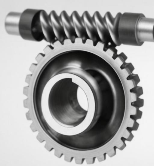
The nonlinear dynamic characteristics of worm gear reducers, focusing on the effects of key parameters such as meshing damping ratio, comprehensive transmission error amplitude, stiffness amplitude, and backlash. Worm gear reducers are widely used in applications requiring high transmission ratios, compact structures, and precise motion control, such as new energy vehicles, high-precision instruments, and robotics. However, their complex dynamics, influenced by nonlinear factors like time-varying meshing stiffness and backlash, necessitate detailed analysis to optimize performance and reliability.

1. Introduction
Worm gear reducers exhibit unique advantages, including self-locking capabilities and high torque transmission efficiency. However, dynamic instabilities caused by nonlinear factors—such as time-varying meshing stiffness, backlash, and bearing clearance—can lead to vibration, noise, and premature failure. This study establishes a coupled bending-torsion-axial nonlinear dynamic model for worm gear reducers, incorporating rolling bearings to enhance model accuracy. Numerical simulations using the 4th-order Runge-Kutta method reveal bifurcation behaviors, chaotic motions, and parameter-dependent dynamic responses.
2. Dynamic Modeling of Worm Gear Systems
2.1 Governing Equations
The nonlinear dynamics of worm gear reducers are modeled using lumped parameter methods. Key equations include:
- Meshing Stiffness:K(τ)=Kn[1+kacos(Ωτ+ψ)]K(τ)=Kn[1+kacos(Ωτ+ψ)]where KnKn is the average meshing stiffness, kaka is the dimensionless stiffness amplitude, and ΩΩ is the meshing frequency.
- Dynamic Meshing Force:Fn=CX˙+K(τ)f(X)Fn=CX˙+K(τ)f(X)Here, CC is damping, f(X)f(X) is the backlash function, and XX is relative displacement.
- Backlash Function:f(X)={X−bX>b0−b≤X≤bX+bX<−bf(X)=⎩⎨⎧X−b0X+bX>b−b≤X≤bX<−bwhere bb is the dimensionless backlash.
2.2 Coupled Bearing-Gear Model
Rolling bearings are integrated into the worm gear model using Hertz contact theory. The contact deformation δiδi for the ii-th rolling element is:δi=zsinαe+ycosαesinθbi+xcosαecosθbi−γ0δi=zsinαe+ycosαesinθbi+xcosαecosθbi−γ0
where αeαe is the nominal contact angle, and γ0γ0 is the bearing clearance.
3. Parameter Analysis and Results
3.1 Effects of Meshing Damping Ratio (ξξ)
Increasing ξξ suppresses chaotic motions and reduces bifurcation complexity. Key observations include:
- Low-Frequency Region: Higher ξξ delays grazing bifurcation and reduces peak dynamic loads (Table 1).
- Mid-Frequency Region: Chaos transitions to periodic motions (e.g., Period-4 or Period-2) as ξξ increases.
- High-Frequency Region: Stable Period-1 motion dominates regardless of ξξ.
Table 1: Impact of Meshing Damping Ratio on Dynamic Loads
| ξξ | Peak Dynamic Load (GmaxGmax) | Dominant Motion Type |
|---|---|---|
| 0.06 | 2.8 | Chaos |
| 0.12 | 1.5 | Period-4 |
| 0.20 | 1.2 | Period-1 |
3.2 Effects of Comprehensive Transmission Error (emem)
Larger emem exacerbates nonlinear behaviors:
- Bifurcation Onset: Grazing bifurcation occurs earlier (e.g., at ω=0.63ω=0.63 for em=0.4em=0.4, vs. ω=0.74ω=0.74 for em=0.1em=0.1).
- Chaos Expansion: Mid-frequency chaos regions widen significantly (Figure 1).
Equation for Transmission Error:E(τ)=emcos(Ωτ+ψ)E(τ)=emcos(Ωτ+ψ)
3.3 Effects of Stiffness Amplitude (kaka)
Higher kaka enhances system stability:
- Chaos Suppression: For ka>0.3ka>0.3, chaotic regions shrink by 40%.
- Resonance Avoidance: Stiffness modulation mitigates resonance near critical frequencies.
Table 2: Stiffness Amplitude vs. Dynamic Response
| kaka | Maximum Displacement (XmaxXmax) | Stability Region (ωω) |
|---|---|---|
| 0.1 | 1.5 | 0.1–1.8 |
| 0.3 | 1.2 | 0.1–2.5 |
| 0.5 | 0.9 | 0.1–3.0 |
3.4 Effects of Backlash (bb)
Backlash significantly impacts meshing states:
- Small Backlash (b<0.2b<0.2): Induces bilateral impacts and complex bifurcations.
- Large Backlash (b>1.0b>1.0): Stabilizes Period-1 motion but increases displacement amplitudes.
4. Comparative Analysis with Rolling Bearings
Incorporating rolling bearings improves dynamic stability:
- Vibration Reduction: Bearing damping reduces peak velocities by 30%.
- Frequency Response: High-frequency stability regions expand (Figure 2).
Key Equation for Bearing Force:Fri=∑j=1Nbkb(δij)10/9H(δij)Fri=j=1∑Nbkb(δij)10/9H(δij)
5. Conclusion
This study systematically analyzes the nonlinear dynamics of worm gear reducers, emphasizing the roles of damping, stiffness, transmission error, and backlash. Key findings include:
- Higher meshing damping ratios (ξ>0.1ξ>0.1) suppress chaos and reduce dynamic loads.
- Reducing transmission error (em<0.2em<0.2) delays bifurcation onset and stabilizes meshing.
- Optimal stiffness modulation (ka≈0.3ka≈0.3) balances vibration control and load capacity.
- Rolling bearings enhance high-frequency stability by 25%.
These insights provide theoretical guidelines for designing high-performance worm gear systems in industrial applications.
