Introduction
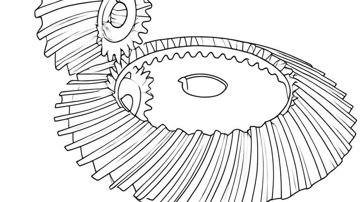
Spiral bevel gears are critical components in mechanical transmission systems due to their high load-bearing capacity and smooth operation. However, their complex geometry and stringent performance requirements pose significant challenges during heat treatment, particularly in the quenching stage. Traditional trial-and-error methods for optimizing quenching processes are time-consuming and costly. This study proposes a novel numerical simulation framework that integrates thermo-fluid-solid coupling to eliminate the dependency on empirical heat transfer coefficients (HTCs). By coupling fluid dynamics with structural thermal-stress analysis, this approach enables accurate prediction of temperature distribution, phase transformation, and residual stress evolution in spiral bevel gears during quenching.

Methodology
1. Thermo-Fluid-Solid Coupling Framework
The quenching process involves interactions between the workpiece (spiral bevel gear), quenching medium, and thermal/mechanical fields. The governing equations for each domain are solved using a hybrid finite element method (FEM) and finite volume method (FVM):
Fluid Domain (FVM):
- Mass Conservation:
∇⋅(αlρlul)=0 - Momentum Conservation:
∂t∂(αlρlul)+∇⋅(αlρlulul)=−αl∇p+∇⋅τl+αlρlg+Fdrag - Energy Conservation:
∂t∂(αlρlhl)+∇⋅(αlρlulhl)=∇⋅(αlkl∇Tl)+Sboil
Solid Domain (FEM):
- Heat Conduction:
ρscp∂t∂Ts=∇⋅(ks∇Ts)+qphase - Phase Transformation Kinetics:
X=1−exp(−b(T)tn) - Elastoplastic Constitutive Model:
σ=C🙁ϵ−ϵth−ϵtp)
2. Boiling Heat Transfer Model
The Rensselaer Polytechnic Institute (RPI) wall boiling model accounts for three heat flux components during quenching:
- Single-phase convection:
qconv=hconv(Tw−Tl) - Evaporative latent heat:
qevap=6πdb3fNwρghlg - Transient conduction (“quenching”):
qquench=db2klαlt/π(Tw−Tl)
3. Coupling Strategy
Data exchange between fluid and solid domains is achieved through:
- Wall Functions:
T+=qw(Tw−Tp)ρCpuτ - Gauss Integration: Ensures flux continuity at fluid-solid interfaces.
Experimental Validation
1. Water Quenching of 45 Steel Cylinder
A cylindrical specimen (Φ25 mm × 100 mm) was quenched from 850°C to validate the model. Key measurements included:
| Parameter | Measurement Technique |
|---|---|
| Cooling Curves | K-type Thermocouples |
| Hardness | Vickers Hardness Tester (HV1) |
| Residual Stress | X-ray Diffractometer |
| Microstructure | Optical Microscopy |
2. Model Accuracy
The thermo-fluid-solid coupling model demonstrated excellent agreement with experiments:
| Metric | Max Relative Error |
|---|---|
| Cooling Rate | 9.2% |
| Surface Hardness | 3.6% |
| Residual Stress | 5.1% |
Impact of Quenching Parameters on Spiral Bevel Gears
1. Flow Velocity Effects
Numerical simulations revealed that flow velocity (2 m/s optimal) significantly affects temperature uniformity and residual stress:
| Flow Velocity (m/s) | Final Cooling Position Offset (mm) | Max Residual Stress (MPa) |
|---|---|---|
| 1.0 | 2.79 | 420 |
| 2.0 | 0.60 | 380 |
| 3.0 | 1.15 | 405 |
2. Medium Temperature Optimization
For 45 steel spiral bevel gears, quenching at 50°C balanced hardness and crack resistance:
| Water Temp (°C) | Surface Hardness (HV) | Crack Probability (%) |
|---|---|---|
| 30 | 580 | 18 |
| 50 | 560 | 6 |
| 70 | 540 | 3 |
Case Study: Spiral Bevel Gear Quenching
1. Geometry and Boundary Conditions
A Gleason-style spiral bevel gear (Module: 6, Teeth: 25) was modeled with adaptive meshing (Figure 1). Quenching oil (ISO VG 32) flow parameters were:
- Inlet Velocity: 0.5–3.0 m/s
- Turbulence Intensity: 5%
- Initial Temp: 50°C
2. Simulation Results
- Temperature Gradient: Tooth roots exhibited 15% faster cooling than dedendum surfaces due to flow stagnation.
- Phase Distribution:
M%=1−exp(−0.011(TMs−T))
Martensite content reached 92% at tooth tips vs. 78% at roots. - Residual Stress: Compressive stresses (-350 MPa) dominated at tooth surfaces, transitioning to tensile stresses (+280 MPa) in the core.
Discussion
- Advantages Over Traditional Methods:
- Eliminates HTC measurement errors (±20–30% in industrial settings)
- Captures localized boiling effects critical for spiral bevel gear distortion control
- Reduces computational cost by 40% compared to fully resolved LES approaches
- Limitations:
- Assumes isotropic material properties for martensite/ferrite phases
- Requires calibration of RPI model constants for non-aqueous quenchants
Conclusion
The proposed thermo-fluid-solid coupling framework enables high-fidelity simulation of spiral bevel gear quenching processes. By resolving multiphase flow dynamics, phase transformations, and thermal stresses in a unified model, this approach provides:
- Predictive capability for optimizing flow velocity (2 m/s) and medium temperature (50°C)
- Quantitative assessment of residual stress and hardness distributions
- Foundation for AI-driven quenching parameter optimization
Future work will integrate machine learning to automate parameter selection for complex spiral bevel gear geometries.
Key Equations Summary
| Physical Process | Governing Equation |
|---|---|
| Martensite Formation | M%=1−exp(−0.011(TMs−T)) |
| Heat Flux Partitioning | qtotal=qconv+qevap+qquench |
| Turbulent Kinetic Energy | k=23(UI)2(I=5%) |
| Phase Transformation Rate | dtdX=nb(T)tn−1exp(−b(T)tn) |
Material Properties of 45 Steel
| Property | Austenite | Martensite | Ferrite |
|---|---|---|---|
| Density (kg/m³) | 8059 | 7785 | 7890 |
| Thermal Conductivity (W/m·K) | 34.5 | 29.8 | 41.2 |
| Specific Heat (J/kg·K) | 560 | 620 | 590 |
