Abstract
Accurate analysis of meshing misalignment in spiral bevel gear transmission systems under load is critical for optimizing gear tooth profiles and ensuring reliable performance. Traditional beam element models often introduce significant errors when analyzing shaft deformation in complex transmission systems, leading to unreliable misalignment predictions. This study proposes a stepwise solid finite element method (FEM) to address these limitations. By coupling bearing stiffness with shaft deformation, applying equivalent gear meshing forces, and constructing a load-dependent contact analysis model, the method achieves high accuracy while improving computational efficiency. Validation against a full FEM model demonstrates alignment in misalignment predictions (errors <2.5%) and a 76.7% reduction in analysis time. Key innovations include refined shaft modeling, force equivalence principles, and adaptive meshing strategies tailored for spiral bevel gear.

1. Introduction
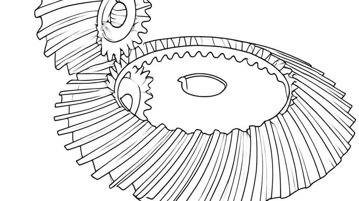
Spiral bevel gear is pivotal components in automotive, aerospace, and marine transmissions due to their high torque capacity and smooth operation. However, system deformations under load induce meshing misalignment, degrading transmission efficiency, noise, and fatigue life. Traditional approaches simplify shafts as beam elements, which fail to capture deformation nuances in structurally complex systems. This work introduces a robust FEM-based methodology to resolve these challenges, emphasizing the unique geometry and loading conditions of spiral bevel gear.
2. Methodology
2.1 Definition of Meshing Misalignment
Meshing misalignment arises from relative displacements between the pinion and gear axes under load. Key parameters include:
- ΔP: Axial displacement of the pinion.
- ΔW: Axial displacement of the gear.
- ΔE: Offset displacement.
- ΔΣ: Angular deviation between axes.
For a deformation vector R’ between initial (O, Q) and deformed (A, B) shaft intersection points, misalignment is calculated as:{ΔP=(R′−ROQ)⋅iΔW=(R′−ROQ)⋅jΔE=(R′−ROQ)⋅kΔΣ=θ2−θ1⎩⎨⎧ΔP=(R′−ROQ)⋅iΔW=(R′−ROQ)⋅jΔE=(R′−ROQ)⋅kΔΣ=θ2−θ1
where i, j, k are unit vectors, and θ1θ1, θ2θ2 represent pre- and post-deformation shaft angles.
2.2 Stepwise Solid FEM Approach
The methodology comprises four stages:
Stage 1: Shaft-Bearing Coupled Model
- Modeling: A 3D solid FEM model of the transmission shaft is constructed, incorporating bearing stiffness as spring constraints (Figure 1).
- Meshing: Hexahedral elements refine critical regions (gear/bearing mounts), reducing mesh count by 40% compared to tetrahedral meshing.
Stage 2: Equivalent Meshing Force Calculation
Gear contact forces are simplified to nodal loads using torque equivalence. For a spiral bevel gear pair with torque TT:Ft=2Tdm,Fa=Fttanβ,Fr=FttanαFt=dm2T,Fa=Fttanβ,Fr=Fttanα
where FtFt, FaFa, and FrFr are tangential, axial, and radial forces; dmdm is the mean diameter; ββ is the spiral angle; and αα is the pressure angle.
Stage 3: Shaft Deformation Analysis
Displacements at key nodes are extracted to compute misalignment parameters. Comparative results between beam and solid FEM models highlight beam inaccuracies (Table 1).
Table 1: Shaft Deformation Errors (Beam vs. Solid FEM)
| Node | Beam Model (mm) | Solid FEM (mm) | Error (%) |
|---|---|---|---|
| 5 | 1.596 | 1.765 | 10.6 |
| 6 | 1.593 | 1.784 | 12.0 |
| 7 | 1.590 | 1.785 | 12.3 |
Stage 4: Loaded Tooth Contact Analysis (LTCA)
Misalignment values adjust gear positions in a simplified LTCA model (Figure 2). Contact pressure and transmission error are evaluated using:σc=FnE∗πρ,Δϕ=σc=πρFnE∗,Δϕ=
where σcσc is Hertzian contact stress, FnFn is normal load, E∗E∗ is equivalent modulus, ρρ is relative curvature, and ΔϕΔϕ is transmission error.
3. Case Study: Automotive Drive Axle
3.1 System Parameters
A spiral bevel gear pair with the following specifications is analyzed:
Table 2: Spiral Bevel Gear Parameters
| Parameter | Pinion | Gear |
|---|---|---|
| Teeth | 7 | 43 |
| Module (mm) | 10.512 | – |
| Pressure Angle | 22.5° | – |
| Spiral Angle | 48.08° | 34.35° |
| Face Width (mm) | 81.61 | 74.00 |
Table 3: Bearing Stiffness Matrix (N/mm)
| Bearing | KxxKxx | KyyKyy | KzzKzz |
|---|---|---|---|
| 1 | 1.47×10⁶ | 6.92×10⁶ | 1.13×10⁶ |
| 2 | 1.40×10⁶ | 5.30×10⁶ | 5.22×10⁶ |
3.2 Misalignment and LTCA Results
The stepwise method achieves <2.5% deviation from the full FEM model:
Table 4: Meshing Misalignment Comparison
| Parameter | Stepwise FEM | Full FEM | Error (%) |
|---|---|---|---|
| ΔP (mm) | 0.0938 | 0.0952 | 1.5 |
| ΔW (mm) | -0.0354 | -0.0362 | 2.2 |
| ΔΣ (°) | 0.0331 | 0.0337 | 1.8 |
LTCA results (Figure 3) show congruent contact patterns and transmission error curves, with a 1.3% amplitude difference.
3.3 Computational Efficiency
The stepwise method reduces mesh count by 60% and computation time by 76.7%:
Table 5: Analysis Time Comparison
| Model | Mesh Count | Time (h) |
|---|---|---|
| Full FEM | 3.08M | 26.2 |
| Stepwise FEM + LTCA | 0.99M | 6.1 |
4. Discussion
The proposed method addresses three critical challenges in spiral bevel gear analysis:
- Accuracy: Solid FEM captures complex shaft deformations neglected by beam models.
- Efficiency: Decoupling shaft and gear analyses minimizes meshing complexity.
- Scalability: The framework adapts to multi-stage gear systems with minimal adjustments.
Limitations include assumptions in bearing stiffness linearity and gear tooth microgeometry. Future work will integrate nonlinear bearing models and stochastic load variations.
5. Conclusion
This study presents a validated stepwise FEM approach for analyzing meshing misalignment in spiral bevel gear transmission systems. By synergizing solid shaft modeling, force equivalence, and adaptive LTCA, the method achieves high fidelity with 76.7% faster computation than full FEM. The results underscore the importance of precision in shaft deformation modeling for spiral bevel gear, enabling optimized tooth profiles and enhanced system longevity.
