Introduction
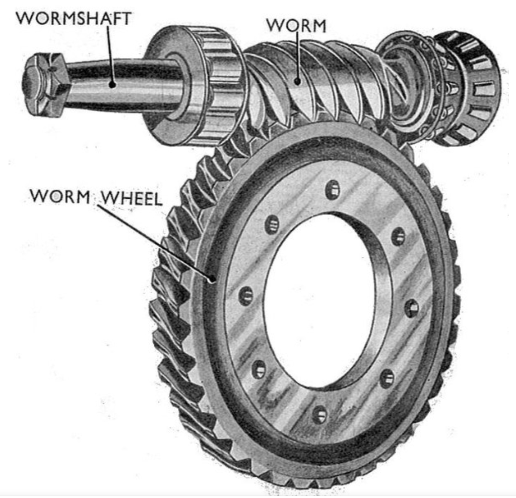
Electric Power Steering (EPS) systems have become increasingly prevalent in modern vehicles due to their energy efficiency, compact design, and superior dynamic control. A critical component in Column-type EPS (C-EPS) systems is the worm gear transmission pair, which amplifies the motor torque to assist steering. However, excessive frictional torque and its fluctuations in the worm gear mechanism can lead to heavy steering feel and discomfort, significantly impacting driving experience. This study investigates the meshing performance of EPS worm gear pairs through finite element analysis (FEA), focusing on factors such as tooth surface errors, friction coefficients, gear deformation, preload variations, and tooth profile modifications.

Methodology
Finite Element Model Development
A 3D finite element model of the EPS worm gear pair was developed using Hypermesh and Abaqus. The model included:
- Worm and Helical Gear: Meshed with hexahedral elements (0.3 mm size) for accuracy.
- Material Properties: Elastic parameters for steel (worm) and PA66 (helical gear) were defined (Table 1).
| Component | Material | Elastic Modulus (MPa) | Poisson’s Ratio |
|---|---|---|---|
| Worm | Steel (51CrV4) | 210,000 | 0.3 |
| Helical Gear | PA66 | 2,200 | 0.4 |
Friction Model: An exponential decay model was adopted to capture static-to-dynamic friction transitions:μ=μk+(μs−μk)e−dcγeqμ=μk+(μs−μk)e−dcγeq
where μs=0.08μs=0.08 (static), μk=0.038μk=0.038 (dynamic), and dc=0.2dc=0.2 (decay coefficient).
Boundary Conditions and Interactions
- Constraints: The worm’s axial displacement and helical gear’s rotational speed (72 RPM) were fixed.
- Contact Pairs: Defined between worm and gear teeth using penalty-based friction.
Key Findings
1. Impact of Tooth Surface Errors
Tooth surface deviations from manufacturing were mapped onto the helical gear using coordinate measurements. The results showed:
- Increased Transmission Error: Deviations amplified fluctuations in meshing force by 35–44%.
- Frictional Torque Variability: Fluctuation range rose from 0.088 Nm (ideal) to 0.127 Nm (with errors).
Formula for Equivalent Meshing Force:Ft=Fx2+Fy2+Fz2Ft=Fx2+Fy2+Fz2
where Fx,Fy,FzFx,Fy,Fz are contact force components.
2. Influence of Friction Coefficients
Simulations with varying friction coefficients (μ=0.02–0.05μ=0.02–0.05) revealed:
- Higher Friction: Increased mean frictional torque from 1.108 Nm (μ=0.02μ=0.02) to 2.680 Nm (μ=0.05μ=0.05).
- Contact Area Expansion: Larger μμ widened the contact zone, raising stress concentrations (Fig. 1).
| Friction Coefficient (μμ) | Starting Torque (Nm) | Mean Torque (Nm) | Fluctuation (Nm) |
|---|---|---|---|
| 0.02 | 2.497 | 1.108 | 0.093 |
| 0.038 | 2.737 | 2.087 | 0.127 |
| 0.05 | 3.149 | 2.680 | 0.150 |
3. Gear Deformation Effects
Thermal deformation of plastic gears under load altered preload conditions:
- Reduced Preload: Deformation lowered contact pressure by 30%, decreasing mean torque to 0.937 Nm.
- Increased Meshing Stiffness: Elastic deformation fluctuations elevated stiffness variability by 29%.
Meshing Stiffness Calculation:Kt=FtutKt=utFt
where utut is the comprehensive elastic deformation.
4. Structural Preload Parameters
Orthogonal experiments evaluated center distance, eccentricity, and bracket stiffness:
- Center Distance Dominance: Reducing center distance from 52.70 mm to 52.34 mm raised torque fluctuation by 460% (0.078 Nm to 0.463 Nm).
- Optimal Preload: A balance between eccentricity (0.5 mm) and bracket thickness (2.5 mm) minimized instability.
| Parameter | Level 1 | Level 2 | Level 3 |
|---|---|---|---|
| Center Distance (mm) | 52.34 | 52.52 | 52.70 |
| Eccentricity (mm) | 0.45 | 0.50 | 0.55 |
| Bracket Thickness (mm) | 2.45 | 2.50 | 2.602 |
5. Tooth Profile Modification
Linear and parabolic modifications were tested:
- Linear Modification: Reduced torque fluctuation by 27% at 0.04 mm trim.
- Parabolic Modification: Increased transmission error by 15% despite similar trimming.
Optimal Trim: 0.04 mm linear modification achieved the lowest fluctuation (0.083 Nm) and transmission error.
Discussion
The worm gear’s meshing performance is highly sensitive to geometric and operational factors. Key insights include:
- Friction Dynamics: Higher friction coefficients amplify torque fluctuations but stabilize contact patterns.
- Deformation-Preload Coupling: Plastic gear deformation reduces preload, necessitating adaptive backlash adjustment.
- Profile Optimization: Linear trimming outperforms parabolic methods in balancing torque stability and transmission accuracy.
Conclusion
This study establishes a validated FEA framework for EPS worm gear systems, highlighting the interplay between friction, deformation, and preload. Key recommendations:
- Manufacturing Precision: Minimize tooth surface errors to curb transmission error.
- Lubrication Strategies: Optimize friction coefficients within 0.02–0.04 for torque stability.
- Adaptive Preload: Incorporate real-time adjustments for thermal deformation compensation.
