Introduction
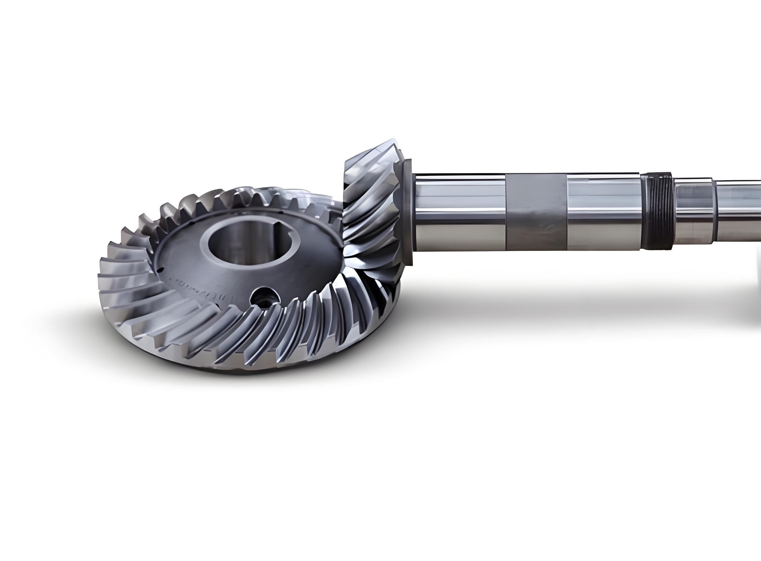
Spiral bevel gear is widely used in aerospace, automotive, and helicopter transmission systems due to their compact structure, high load-bearing capacity, and low noise. However, conventional gear machining methods face challenges in processing spiral bevel gear with large helix angles. Existing techniques, such as hobbing or grinding, often result in insufficient precision or limited applicability for high-helix-angle geometries. To address this gap, we propose a two-degree-of-freedom (2-DOF) skiving method tailored for spiral bevel gear. This approach integrates the advantages of both hobbing and shaping, enabling precise machining of large-helix-angle spiral bevel gear.

Theoretical Framework
Installation Layout of Skiving Components
The skiving system comprises three key components: the skiving cutter, an imaginary helical generating gear, and the spiral bevel gear workpiece. The cutter and workpiece are arranged in a staggered-axis configuration, ensuring point contact during machining. The geometric relationship between these components is governed by the following parameters:
- Axis angle (γ): Determined by the helix angle (β) of the imaginary generating gear:γ=β(1)γ=β(1)
- Relative motion: The cutter and workpiece perform synchronized rotational and translational motions to generate the desired tooth profile.
Kinematic Analysis
The skiving process involves two independent motions:
- Generating motion: The spiral bevel gear rotates around its axis (z2z2) at angular velocity ω2ω2, while the cutter rotates around its axis (zszs) at ωsωs.
- Feed motion: The cutter translates along the axis of the imaginary generating gear (zgzg) by a distance ss after each generating cycle.
The relationship between angular velocities is defined as:i2s=ω2ωs=NsN2(2)i2s=ωsω2=N2Ns(2)
where NsNs and N2N2 represent the number of teeth on the cutter and workpiece, respectively.
Mathematical Modeling
Meshing Equations
Using differential geometry and meshing theory, we derive the equations governing the contact between the cutter and spiral bevel gear. The position vector of the cutter’s cutting edge in coordinate system SsSs is expressed as:rsk(θs)=[τrbssin(θs+θas)−θscos(θs+θas)−τrbscos(θs+θas)−θssin(θs+θas)01](k=I,II)(3)rsk(θs)=τrbssin(θs+θas)−θscos(θs+θas)−τrbscos(θs+θas)−θssin(θs+θas)01(k=I,II)(3)
Here, rbsrbs is the base circle radius, θsθs is the rotation angle, and θasθas is the pressure angle correction term:θas=π2Ns−tanα+α(4)θas=2Nsπ−tanα+α(4)
The meshing condition is derived by ensuring the relative velocity vector lies on the common tangent plane:fzk(θs,ϕs,s)=(∂rzk∂θs×∂rzk∂ϕs)⋅∂rzk∂s=0(k=I,II)(5)fzk(θs,ϕs,s)=(∂θs∂rzk×∂ϕs∂rzk)⋅∂s∂rzk=0(k=I,II)(5)
Tooth Surface Equations
The working tooth surface (Σ2Σ2) of the spiral bevel gear is generated by solving the system:{rzk(θs,ϕs,s)=Mzk(ϕs,s)⋅rsk(θs)s=s(θs,ϕs)(k=I,II)(6){rzk(θs,ϕs,s)=Mzk(ϕs,s)⋅rsk(θs)s=s(θs,ϕs)(k=I,II)(6)
where MzkMzk represents the coordinate transformation matrix.
Error Analysis
To evaluate the feasibility of the 2-DOF skiving method, we analyze deviations between the skived and theoretical tooth surfaces. The normal error (δδ) at discrete points is calculated as:δ=nz⋅(rzk−rzk∗)(7)δ=nz⋅(rzk−rzk∗)(7)
Here, nznz is the unit normal vector, and rzk∗rzk∗ denotes the theoretical position vector.
Simulation Results
Table 1 summarizes the geometric parameters and error ranges for two helix angle cases.
Table 1: Error analysis for spiral bevel gear with different helix angles
| Parameter | Case 1 (β=15∘β=15∘) | Case 2 (β=25∘β=25∘) |
|---|---|---|
| Number of cutter teeth (NsNs) | 27 | 32 |
| Module (mm, mm) | 3.25 | 3.25 |
| Pressure angle (αα, °) | 20 | 20 |
| Convex flank error (mm) | −0.011∼−0.017−0.011∼−0.017 | −0.01∼−0.02−0.01∼−0.02 |
| Concave flank error (mm) | 0∼0.0050∼0.005 | 0∼0.0030∼0.003 |
The results confirm that concave flank errors are negligible, while convex flank errors remain within acceptable limits (<0.02<0.02 mm), validating the 2-DOF skiving principle.
Conclusion
This study presents a novel 2-DOF skiving method for machining spiral bevel gear with large helix angles. By establishing kinematic and mathematical models, we demonstrate the method’s capability to achieve high precision and low tooth surface errors. Future work will focus on optimizing cutter geometry and expanding the method to non-orthogonal axis configurations.
Key Equations Summary
- Axis angle relationship:γ=βγ=β
- Angular velocity ratio:i2s=NsN2i2s=N2Ns
- Normal error calculation:δ=nz⋅(rzk−rzk∗)δ=nz⋅(rzk−rzk∗)
Applications and Future Directions
The proposed method holds significant potential for aerospace and automotive industries, where high-performance spiral bevel gear is critical. Future research will explore adaptive control strategies to further minimize machining errors and enhance process efficiency.
