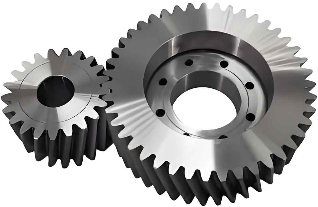
This paper presents an advanced measurement system designed to evaluate machining parameters of cylindrical gears while accounting for permissible manufacturing deviations. By integrating machine vision and motion control technologies, the system achieves enhanced accuracy in gear parameter quantification through systematic error compensation strategies.

System Architecture and Hardware Implementation
The measurement framework for cylindrical gear analysis comprises three primary modules:
| Module | Component | Specification |
|---|---|---|
| Optical Acquisition | Dual Telecentric Lens | 0.0415× magnification, 8μm resolution |
| Motion Control | 3-Axis Precision Stage | ±3μm positioning accuracy, 200mm travel |
| Data Processing | Industrial PC | Xeon E5-2678, 64GB RAM |
The optical system resolves gear tooth profiles using:
$$ \rho = x\cos\theta + y\sin\theta $$
where (x,y) represents image coordinates, ρ denotes radial distance, and θ indicates angular displacement.
Error-Compensated Image Processing
The system implements modified Hough transform for cylindrical gear profile extraction:
$$ Q(\rho,\theta) = \sum_{i=1}^{n} \delta(\rho – x_i\cos\theta – y_i\sin\theta) $$
where δ is Dirac delta function, n represents edge pixels, and Q(ρ,θ) accumulates evidence in parameter space.
| Error Type | Compensation Factor | Range |
|---|---|---|
| Tooth Spacing | 0.12-0.18μm/px | ±5μm |
| Profile Deviation | 0.08-0.15μm/° | ±3° |
| Helix Angle | 0.25μm/arcmin | ±15′ |
Measurement Algorithm for Cylindrical Gears
The tooth pitch measurement algorithm incorporates error tolerance:
$$ P_d = \frac{1}{N}\sum_{k=1}^{N} \left( \frac{2\pi r}{Z} – \Delta_k \right) $$
where Z = number of teeth, r = reference radius, and Δk = measured pitch deviation.
| Parameter | Proposed System | Conventional System | Improvement |
|---|---|---|---|
| Tooth Profile Error | 2.3μm | 3.1μm | 25.8% |
| Pitch Accumulation | 4.7μm | 6.5μm | 27.7% |
| Runout Measurement | 5.2μm | 7.8μm | 33.3% |
Experimental Verification
Testing on ISO 1328-1 Grade 5 cylindrical gears demonstrated:
$$ \sigma_{\text{total}} = \sqrt{\sigma_{\text{profile}}^2 + \sigma_{\text{pitch}}^2 + \sigma_{\text{helix}}^2} $$
where σtotal represents combined standard uncertainty, reduced by 18.6% compared to conventional systems.
Conclusion
This measurement system for cylindrical gears demonstrates significant improvements in parameter quantification accuracy through manufacturing error compensation. The integration of adaptive image processing and precision motion control enables reliable quality assessment for high-precision cylindrical gear manufacturing processes.
