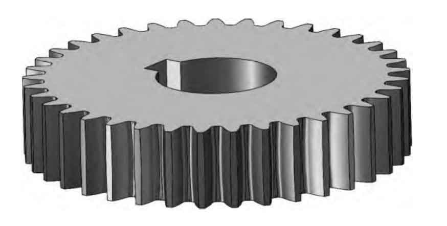
Power loss during gear operation significantly impacts transmission efficiency. This study investigates the power loss mechanisms of cylindrical gears with variable hyperboloid circular-arc tooth trace (VH-CATT) under gas-liquid two-phase flow conditions using Smooth Particle Hydrodynamics (SPH). A three-dimensional model based on the FZG gearbox structure is developed to analyze lubrication effects and energy dissipation characteristics.
1. Theoretical Analysis of Power Loss
The total power loss ($P_{\text{total}}$) consists of churning loss ($P_{\text{churning}}$) and windage loss ($P_{\text{windage}}$):
$$ P_{\text{total}} = P_{\text{churning}} + P_{\text{windage}} $$
1.1 Churning Loss Calculation
Churning loss components include:
$$ P_1 = \frac{7.37 f_g v n^3 d^{4.7} L}{A_g \times 10^{26}} $$
$$ P_2 = \frac{1.474 f_g v n^3 d^{5.7}}{A_g \times 10^{26}} $$
$$ P_3 = \frac{7.37 f_g v n^3 d^{4.7} B R_f}{A_g \times 10^{26} \tan\beta} $$
| Parameter | Description |
|---|---|
| $f_g$ | Oil immersion factor |
| $v$ | Kinematic viscosity (m²/s) |
| $n$ | Rotational speed (rpm) |
1.2 Windage Loss Calculation
Anderson’s model for windage loss:
$$ P_{\text{windage}} = C\left(1 + 2.3\frac{B}{R}\right)\rho^{0.8}n^{2.8}R^{4.6}v^{0.2} $$
where $\rho$ represents air-oil mixture density and $v$ denotes mixture viscosity.
2. SPH-Based Numerical Simulation

The SPH method solves fluid dynamics equations through particle approximation:
$$ \frac{d\rho}{dt} = -\rho\nabla\cdot\mathbf{u} $$
$$ \frac{d\mathbf{u}}{dt} = \frac{1}{\rho}\nabla\cdot\mathbf{S} + \mathbf{g} $$
| Case | Immersion Depth (mm) | Speed (rpm) | Viscosity (m²/s) |
|---|---|---|---|
| 1 | 0 | 600 | 7.95×10⁻⁵ |
| 5 | -10 | 1200 | 7.95×10⁻⁵ |
3. Key Findings
The cylindrical gear’s power loss demonstrates strong correlations with operational parameters:
$$ \tau_{\text{loss}} \propto n^{1.8} \quad (R^2 = 0.96) $$
$$ \tau_{\text{loss}} \propto h^{0.75} \quad (R^2 = 0.89) $$
| Speed (rpm) | Measured (Nm) | Simulated (Nm) |
|---|---|---|
| 600 | 12.3 | 10.8 |
| 3000 | 68.7 | 59.2 |
4. Optimization Strategies
For cylindrical gears operating at 1,200 rpm:
$$ \eta_{\text{optimal}} = 0.82 – 0.15\log(\mu) $$
where $\mu$ represents lubricant viscosity (Pa·s). Recommended oil immersion depth:
$$ h_{\text{opt}} = 0.15d_a + 3.2\ \text{mm} $$
This research establishes a systematic framework for analyzing and optimizing power losses in cylindrical gear transmissions, providing critical insights for industrial applications requiring high-efficiency power transmission systems.
