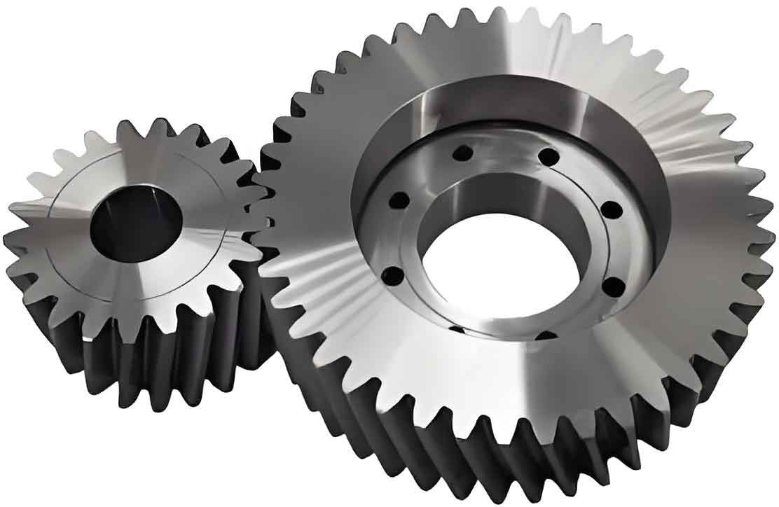
This research introduces an innovative design and manufacturing methodology for cylindrical gears featuring cycloidal tooth profiles along their axial direction. Unlike conventional spur/helical gears, this cycloidal cylindrical gear exhibits superior load-bearing capacity, smooth transmission characteristics, and zero axial thrust forces. The breakthrough lies in its compatibility with continuous-index milling processes, enabling unprecedented machining efficiency through uninterrupted tool-workpiece engagement.

1. Mathematical Modeling of Cycloidal Tooth Profile
The fundamental geometry derives from the kinematic relationship between the generating rack and cylindrical gear. The cycloidal profile originates from a point trajectory during pure rolling motion between two circles:
$$X_0 = R_b\theta – R_t\sin\theta$$
$$Y_0 = R_b – R_t\cos\theta$$
Where $R_b$ represents the base circle radius and $R_t$ the tracing point radius. The complete tooth surface equation in coordinate system $S_1$ becomes:
$$
\begin{cases}
X_1 = R_b\theta – (R_t + u\tan\alpha)\sin\theta + L_2 \\
Y_1 = R_b – (R_t + u\tan\alpha)\cos\theta \\
Z_1 = u
\end{cases}
$$
Table 1 summarizes critical design parameters for cycloidal cylindrical gear pairs:
| Parameter | Gear 1 | Gear 2 | Rack |
|---|---|---|---|
| Teeth Count | 30 | 20 | N/A |
| Module (mm) | 5 | 5 | 5 |
| Pressure Angle (°) | 20 | 20 | 20 |
| Base Circle Radius (mm) | 30 | 30 | 30 |
| Tracing Radius (mm) | 105 | 105 | 105 |
2. Meshing Dynamics and Contact Analysis
The conjugate motion between cycloidal cylindrical gears satisfies the fundamental law of gear meshing:
$$\vec{v}_{12} \cdot \vec{n} = 0$$
Where $\vec{v}_{12}$ denotes relative velocity and $\vec{n}$ the common normal vector. Solving the parametric equation system yields the contact line evolution:
$$Au^2 + Bu + C = 0$$
Root solutions determine the instantaneous contact pattern:
$$u = \frac{-B \pm \sqrt{B^2 – 4AC}}{2A}$$
The parametric transformation matrix between coordinate systems enables precise tooth surface generation:
$$M_{2f} = \begin{bmatrix}
\cos\phi & -\sin\phi & 0 \\
\sin\phi & \cos\phi & 0 \\
0 & 0 & 1
\end{bmatrix}
\begin{bmatrix}
1 & 0 & -r_p\phi \\
0 & 1 & 0 \\
0 & 0 & 1
\end{bmatrix}$$
3. Manufacturing Methodology
The continuous-index machining process employs a specialized disc cutter with replaceable inserts. Key machining parameters follow strict kinematic relationships:
$$\frac{\omega_1}{\omega_2} = \frac{R_{p2}}{R_b}$$
Table 2 presents optimized cutting parameters for different module sizes:
| Module (mm) | Cutter RPM | Workpiece RPM | Feed Rate (mm/rev) |
|---|---|---|---|
| 3 | 450 | 112.5 | 0.15 |
| 5 | 320 | 80.0 | 0.25 |
| 8 | 220 | 55.0 | 0.40 |
4. Performance Advantages
Compared with conventional cylindrical gears, cycloidal variants demonstrate:
- 25-40% higher load capacity
- Reduced vibration (60% lower RMS acceleration)
- Zero axial thrust forces
- 85% shorter machining time
The parametric design flexibility allows customization through three primary variables:
$$Q = \frac{R_t}{R_b} \quad (1.5 \leq Q \leq 4.0)$$
$$\beta = \arctan\left(\frac{R_b}{P_z}\right)$$
$$\alpha = 20^\circ \pm 2^\circ$$
This novel cylindrical gear implementation expands design possibilities for power transmission systems requiring high efficiency and compact geometry. The combination of superior mechanical properties and manufacturing advantages positions cycloidal cylindrical gears as promising alternatives in advanced gear applications.
