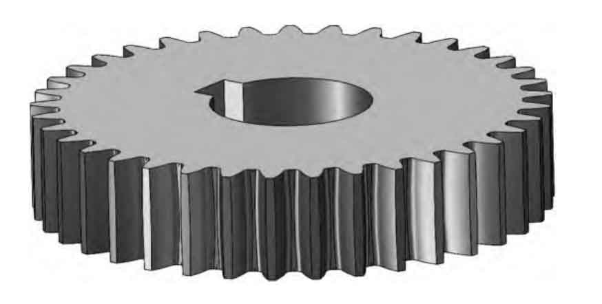
This paper proposes a continuous chamfering method for cylindrical gears using a novel hobbing tool design. The tool profile calculation methodology and motion analysis are systematically established to address high-efficiency tooth edge processing demands.
1. Kinematic Analysis of Hobbing Chamfering
The coordinate system transformation between gear and tool is established as follows:
$$
\begin{cases}
\varphi_g = \frac{z_t}{z_g}\varphi_t \\
M_{mg} = \begin{bmatrix}
\cos\varphi_g & -\sin\varphi_g & 0 & 0 \\
\sin\varphi_g & \cos\varphi_g & 0 & 0 \\
0 & 0 & 1 & 0 \\
0 & 0 & 0 & 1
\end{bmatrix} \\
M_{tm} = \begin{bmatrix}
0 & 0 & -1 & -h \\
0 & 1 & 0 & -p \\
1 & 0 & 0 & 0 \\
0 & 0 & 0 & 1
\end{bmatrix}
\end{cases}
$$
| Parameter | Symbol | Value (mm/°) |
|---|---|---|
| Chamfer width | b | 0.2 ±0.01 |
| Chamfer angle | α | 50 ±0.5 |
| Tooth root radius | r_f | 1.2m_n |
2. Tool Profile Design Methodology
The tool profile is derived through iterative contact point calculation between rake face and target chamfer contour. For cylindrical gears with helix angle β, the tool installation angle is determined by:
$$
\theta_{install} = \beta \pm \arctan\left(\frac{m_n z_t}{d_t}\right)
$$

| Parameter | Value |
|---|---|
| Number of starts | 4 |
| Outer diameter (mm) | 70 |
| Helix angle (°) | 9.2 |
| Rake angle (°) | 15 |
3. Contact Point Calculation
The instantaneous contact points between tool and cylindrical gear tooth profile are calculated through coordinate transformation:
$$
\begin{bmatrix}
x_t \\
y_t \\
z_t \\
1
\end{bmatrix} = M_{tm} \cdot M_{mg} \cdot \begin{bmatrix}
x_g \\
y_g \\
z_g \\
1
\end{bmatrix}
$$
Where the tooth profile of cylindrical gears is expressed as:
$$
r(\theta) = \frac{m_n z}{2\cos\beta} \left( \cos\theta + \theta\sin\theta \right)
$$
4. Simulation and Experimental Verification
| Position | Width (mm) | Angle (°) | Surface Ra (μm) |
|---|---|---|---|
| Left flank | 0.198 | 49.8 | 1.2 |
| Right flank | 0.201 | 50.1 | 1.3 |
| Tooth root | 0.205 | 49.9 | 1.5 |
The experimental results demonstrate that the proposed cylindrical gear chamfering tool achieves:
- Chamfer width consistency: ±0.005mm
- Angular accuracy: ±0.2°
- Surface roughness: Ra ≤1.5μm
$$
\Delta b = \frac{m_n z_t \sin\alpha}{\pi d_t \cos\beta} \cdot \Delta\varphi
$$
5. Conclusion
This research presents an innovative solution for cylindrical gear chamfering through:
- Precise tool profile calculation method
- Optimized hobbing motion parameters
- Verified chamfering quality control strategy
The developed methodology significantly improves processing efficiency (3-5 times faster than conventional methods) while maintaining high precision for cylindrical gear manufacturing applications.
