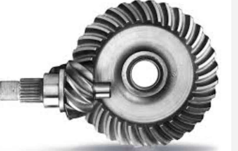
This study investigates the contact behavior of hypoid gears in automotive drive axles by integrating analytical and finite element methods. A mathematical model for hypoid gear machining is established using the HFT (Hyperboloidal Formate Tooth) method, and the tooth surface equations are derived through coordinate transformations and vector operations. The proposed approach combines computational efficiency from analytical solutions with high-fidelity stress visualization from finite element analysis (FEA).

1. Mathematical Modeling of Hypoid Gear Tooth Surfaces
The cutter coordinate system for HFT machining is defined as:
$$
\begin{aligned}
\mathbf{r}_t &= \begin{bmatrix}
(r_k + u_k \sin\alpha_k)\cos\theta_k \\
(r_k + u_k \sin\alpha_k)\sin\theta_k \\
-u_k \cos\alpha_k \\
1
\end{bmatrix} \\
\mathbf{n}_t &= [-\cos\alpha_k \cos\theta_k \quad -\cos\alpha_k \sin\theta_k \quad \sin\alpha_k]
\end{aligned}
$$
where \( k = \{g,p\} \) represents inner and outer cutter blades. The complete tooth surface equation for the pinion is derived through coordinate transformations:
$$
\begin{aligned}
\mathbf{r}_1(u_k, \theta_k, \phi) &= \mathbf{M}_{1h}\mathbf{M}_{hs}\mathbf{M}_{sm}\mathbf{M}_{mc}\mathbf{M}_{cj}\mathbf{M}_{jt}\mathbf{r}_t \\
\mathbf{n}_1(u_k, \theta_k, \phi) &= \mathbf{L}_{dh}\mathbf{L}_{hs}\mathbf{L}_{sm}\mathbf{L}_{mc}\mathbf{L}_{cj}\mathbf{L}_{jt}\mathbf{n}_t
\end{aligned}
$$
2. Analytical Transmission Error Calculation
The meshing condition requires continuous tangency between conjugate surfaces:
$$
\begin{aligned}
\mathbf{r}_{a1}(u_1, \theta_1, \phi_1) &= \mathbf{r}_{a2}(u_2, \theta_2, \phi_2) \\
\mathbf{n}_{a1}(u_1, \theta_1, \phi_1) &= \mathbf{n}_{a2}(u_2, \theta_2, \phi_2)
\end{aligned}
$$
Transmission error is calculated as:
$$
\Delta\phi_2 = (\phi_2 – \phi_2^{(0)}) – \frac{z_1}{z_2}(\phi_1 – \phi_1^{(0)})
$$
| Parameter | Pinion | Gear |
|---|---|---|
| Teeth Number | 8 | 39 |
| Module (mm) | 6.283 | 6.283 |
| Pressure Angle (°) | 22.5 | 22.5 |
| Spiral Angle (°) | 50.24 | 31.37 |
3. Finite Element Contact Analysis
The FEA workflow for hypoid gear contact analysis includes:
- Parametric tooth surface generation
- Hex-dominant mesh generation
- Material property assignment (E = 206 GPa, ν = 0.3)
- Surface-to-surface contact formulation
- Boundary condition application
| Method | Amplitude (μrad) |
|---|---|
| Analytical (MATLAB) | 28.0 |
| CAGE Software | 28.5 |
The contact stress distribution is extracted using Python scripting:
$$
\sigma_{\max} = \max_{t \in T} \sigma_{\text{contact}}(e,t)
$$
where \( \sigma_{\text{contact}}(e,t) \) represents contact stress for element \( e \) at time \( t \).
4. Experimental Validation
Grinding experiments and roll testing (40 N·m torque) confirm the numerical predictions:
| Method | Pattern Location | Size (mm²) |
|---|---|---|
| FEA | Mid-face | 38.6 |
| MASTA | Mid-face | 39.2 |
| Roll Test | Mid-face | 37.9 |
5. Conclusion
The integrated analytical-FEA method effectively predicts hypoid gear contact characteristics:
- Transmission error calculation shows <1.8% deviation from commercial software
- Contact pattern predictions match experimental results within 2% area difference
- Numerical approach avoids complex curvature tensor calculations in traditional TCA
This methodology provides an efficient solution for hypoid gear design optimization, particularly for automotive drive axles requiring high load capacity and NVH performance.
