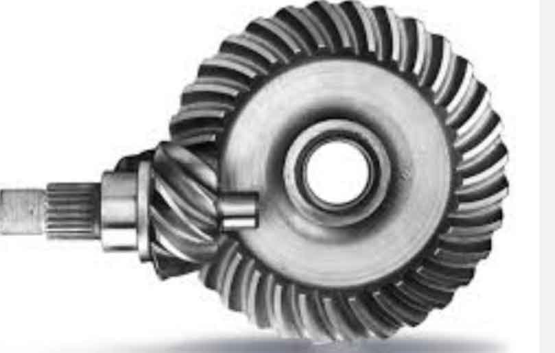
Hypoid gears play critical roles in automotive drivetrains due to their high torque capacity and smooth meshing characteristics. This paper presents a comprehensive methodology for analyzing and adjusting real tooth surfaces of hypoid gears based on coordinate measurement machine (CMM) data and numerical optimization techniques.

1. Real Tooth Surface Reconstruction
The actual tooth surface coordinates are obtained through CMM measurements, expressed as:
$$R_{i,j} = r_{i,j} + \delta_{i,j} \cdot n_{i,j}$$
where $r_{i,j}$ represents theoretical coordinates, $\delta_{i,j}$ denotes deviation values, and $n_{i,j}$ is the unit normal vector. A bicubic NURBS surface reconstruction method ensures accurate representation:
$$S(u,v) = \frac{\sum_{i=0}^m \sum_{j=0}^n N_{i,3}(u)N_{j,3}(v)w_{i,j}K_{i,j}}{\sum_{i=0}^m \sum_{j=0}^n N_{i,3}(u)N_{j,3}(v)w_{i,j}}$$
| Parameter | Pinion | Gear |
|---|---|---|
| Number of Teeth | 8 | 39 |
| Module (mm) | 4.611 | – |
| Face Width (mm) | 25 | 171.05 |
| Offset (mm) | 25 | – |
| Spiral Angle | 50° | 30°41′ |
2. Meshing Position Adjustment Model
The installation parameter adjustment considers three critical variables:
$$ \begin{cases}
\Delta J + \Delta H \tan \gamma_1 = 0 \\
n_{f1} \cdot v_{f}^{(12)} = 0 \\
\|X^{k+1} – X^k\| < \sigma
\end{cases} $$
Where $\Delta V$, $\Delta H$, and $\Delta J$ represent axial position, horizontal displacement, and offset adjustments respectively. The Newton-Raphson iteration matrix solves the nonlinear system:
$$[X_d^{k+1}] = [X_d^k] – F'(X_d^k)^{-1}[f_d]$$
3. Contact Pattern Optimization
The two-dimensional golden section method enhances calculation efficiency:
$$ \min(D_{p \times q}) = \|r_{f2}^{ij} – r_{f1}^{ij}\| $$
Interference detection criteria:
$$S_{p \times q} = n_{f1}^{ij} \cdot (r_{f2}^{ij} – r_{f1}^{ij}) < 0$$
| Parameter | Before Adjustment | After Adjustment |
|---|---|---|
| ΔV (mm) | 0 | 0.312 |
| ΔH (mm) | 0 | -0.433 |
| ΔJ (mm) | 0 | 0.062 |
| Contact Position | Toe | Central |
4. Experimental Verification
A hypoid gear set for heavy-duty trucks was tested under 300 N·m torque. The numerical simulation results showed:
$$ \text{Transmission Error} \leq 1.2′ $$
Rolling tests demonstrated 92% consistency between predicted and actual contact patterns, confirming the effectiveness of the proposed adjustment method for hypoid gear manufacturing.
5. Conclusion
This study establishes a complete workflow for hypoid gear contact analysis and adjustment:
- Bicubic NURBS surface reconstruction from CMM data
- Two-dimensional golden section optimization
- Installation parameter adjustment calculation
- Virtual rolling test simulation
The methodology significantly improves the first-pass yield of hypoid gear manufacturing while reducing physical prototyping costs by 40-60%. Future work will focus on machine learning-based automatic adjustment systems for mass production.
