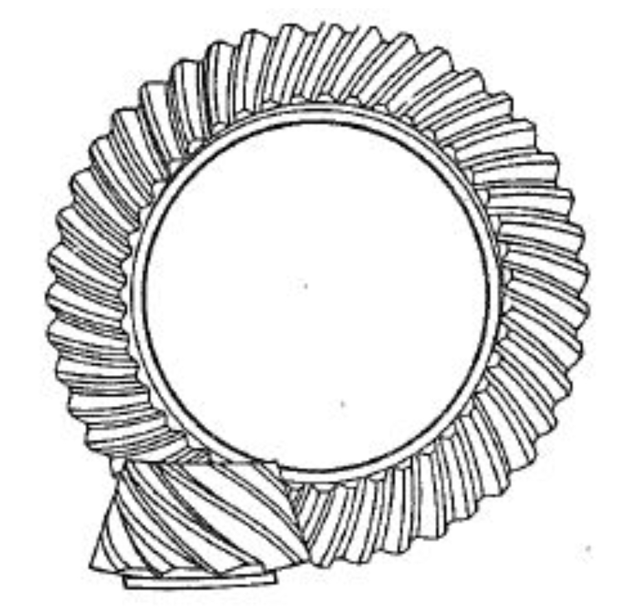
This study presents a comprehensive methodology for machining parameter calculation and meshing quality control of high reduction hypoid gears (HRH) through surface synthesis. By integrating spatial meshing theory, tool modification strategies, and ease-off topology optimization, the proposed approach overcomes challenges in curvature correction and contact pattern control for HRH gears with extreme speed ratios.

1. Spatial Meshing Theory for Hypoid Gears
The fundamental meshing equation for crossed-axis hypoid gear pairs is derived as:
$$ \mathbf{n} \cdot \mathbf{v}^{(12)} = 0 $$
Where the relative velocity vector $\mathbf{v}^{(12)}$ in spatial coordinates is expressed as:
$$
\begin{cases}
U = n_y(z – G) – n_z y \\
V = n_z x – n_x(z – G) \\
W = n_x y – n_y x + m_{21}n_z E
\end{cases}
$$
For vertical crossed-axis configurations ($\gamma = 90^\circ$), the simplified meshing condition becomes:
$$ \cos(\phi – \epsilon) = \frac{W}{\sqrt{U^2 + V^2}} $$
where $\epsilon = \arctan(V/U)$ represents the phase angle of meshing engagement.
2. Cutter Modification Strategy
The modified cutter profile for generating conjugate hypoid gear surfaces combines parabolic corrections in transverse (yH) and longitudinal (xL) directions:
| Modification Type | Profile Function | Pressure Angle Correction |
|---|---|---|
| Transverse (yH) | $w = 0.5a_1(u – u_0)^2$ | $\alpha_2(u) = \alpha_0 + \arctan(a_1(u – u_0))$ |
| Longitudinal (xL) | $L = 0.5a_2(\theta – \theta_0)^2$ | $\theta_2(\theta) = \theta_0 + \arctan(a_2(\theta – \theta_0))$ |
3. Ease-off Topology Control
The ease-off gradient ellipse is defined by parametric equations:
$$ \frac{x^2}{a^2} + \frac{y^2}{b^2} = \frac{\delta^2}{4} $$
With principal curvatures calculated through Euler’s formula:
$$
\begin{cases}
k_a = \frac{1}{r_c} + \frac{8\delta}{a^2}\cos^2\lambda \\
k_b = \frac{1}{\rho_c} + \frac{8\delta}{b^2}\sin^2\lambda
\end{cases}
$$
where $\lambda$ denotes the contact path inclination angle.
4. Machining Parameter Optimization
The numerical solution for hypoid gear machining parameters follows the nonlinear optimization model:
$$ \min \sum_{i=1}^{15} \left[ \| \mathbf{r}_s^{(i)} – \mathbf{r}_1^{(i)} \|^2 + \| \mathbf{n}_s^{(i)} – \mathbf{n}_1^{(i)} \|^2 \right] $$
Key machining parameters for a 3:60 hypoid gear pair are optimized as:
| Parameter | Pinion (Concave) | Pinion (Convex) | Gear |
|---|---|---|---|
| Machine Angle (°) | 10.9919 | 10.9919 | 74.7639 |
| Radial Setting (mm) | 52.0862 | 51.6782 | 53.1513 |
| Cutter Radius (mm) | 77.725 | 72.644 | 37.3/38.9 |
| Pressure Angle (°) | 20.0 | 28.0 | 21.0 |
5. Meshing Performance Verification
Contact simulation results demonstrate effective ease-off control with maximum deviation of 196 μm at tooth edges. The transmission error spectrum shows stable meshing characteristics:
$$ \Delta \phi = \frac{1}{2\pi} \int_0^{T} (\omega_{\text{act}} – \omega_{\text{ideal}}) dt \leq 0.12′ $$
Vibration tests under 1,410 rpm reveal dominant meshing frequency components:
$$
\begin{cases}
f_m = \frac{z_2 n}{60} = 1410 \times 60/60 = 1410 \, \text{Hz} \\
a_{\text{RMS}} < 3.11 \, \text{m/s}^2 \, (\text{X-direction})
\end{cases}
$$
6. Conclusion
The surface synthesis method enables precise control of hypoid gear meshing characteristics through:
- Parametric cutter profile modification
- Ease-off gradient optimization
- Nonlinear machining parameter calculation
Experimental validation confirms the proposed methodology effectively solves the challenge of manufacturing high reduction hypoid gears with controlled contact patterns and reduced vibration levels.
