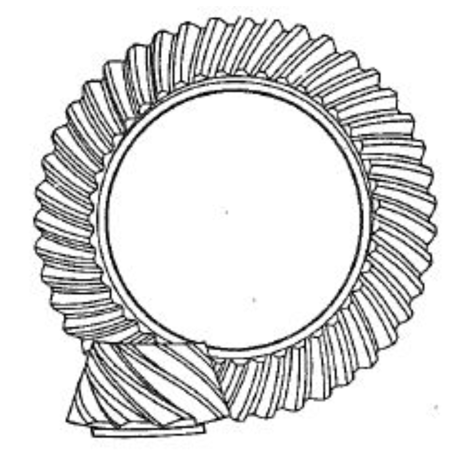
Hypoid gears are widely used in automotive, aerospace, and industrial machinery due to their high load capacity, smooth transmission, and compact structure. This study focuses on designing and analyzing hypoid gears with fewer than five pinion teeth and reduction ratios exceeding 10:1. A systematic approach integrating geometric design, 3D simulation, and machining experiments is presented to address challenges such as tooth undercutting, tip sharpening, and meshing interference.

1. Geometric Design Constraints for Hypoid Gears
The design of hypoid gears with high reduction ratios requires consideration of critical constraints:
$$z_{v1} = \frac{z_1}{\cos^3\beta_{m1}} \geq 20$$
$$b_{a1} \geq 0.4m_n$$
$$W_2 = s_{n1} – h_{f2}(\tan\alpha_{f1} – \tan\alpha_{f2}) \geq 0.4m_n$$
Orthogonal analysis reveals key factors affecting pitch cone angles:
| Factor | Level 1 | Level 2 | Level 3 |
|---|---|---|---|
| Spiral angle (°) | 56 | 59 | 62 |
| Cutter radius (mm) | 82.9 | 88.9 | 94.9 |
| Tooth depth coefficient | 2.5 | 3.0 | 3.5 |
2. Tooth Surface Generation
The mathematical model for hypoid gear generation considers formate cutting and conjugate surface theory. For gear tooth surface coordinates:
$$x_2 = (r_0 \sin\alpha – u_g \cos\alpha)\cos\gamma_m + H_2 \sin\gamma_m$$
$$y_2 = V_2 – u_g \sin\theta_g$$
$$z_2 = (r_0 \sin\alpha – u_g \cos\alpha)\sin\gamma_m – H_2 \cos\gamma_m – x_{g2}$$
Pinion surface equations derived through conjugate meshing conditions:
$$v_{21} \cdot n_2 = \omega_{21} \times r_2 \cdot n_2 – (\omega_2 – \omega_1) \cdot (E \times n_2) = 0$$
3. 3D Modeling Methodology
A structured grid system converts 2D projections to 3D coordinates:
| Parameter | Gear | Pinion (4:41) | Pinion (3:60) |
|---|---|---|---|
| Teeth count | 41 | 4 | 3 |
| Spiral angle (°) | 28.5 | 59.0 | 72.0 |
| Face angle (°) | 82.1 | 10.7 | 7.4 |
Coordinate transformation matrix for UG modeling:
$$M_{12} = \begin{bmatrix}
-\sin\phi_2 & -\cos\phi_2 & 0 \\
\cos\phi_1\cos\phi_2 & -\cos\phi_1\sin\phi_2 & -\sin\phi_1 \\
\sin\phi_1\cos\phi_2 & -\sin\phi_1\sin\phi_2 & \cos\phi_1
\end{bmatrix}$$
4. Machining Experiments
Critical machine settings for 4:41 hypoid gear pair:
| Parameter | Gear | Pinion (concave) | Pinion (convex) |
|---|---|---|---|
| Machine root angle (°) | 76.9 | -3.3 | -3.5 |
| Radial position (mm) | 49.1 | 54.2 | 55.7 |
| Swivel angle (°) | 96.2 | 194.7 | 196.3 |
Transmission error analysis shows satisfactory contact patterns:
$$TE = \frac{\Delta\phi_2}{i_{21}} – \Delta\phi_1 \leq 1’$$
5. Conclusion
This study successfully demonstrates the feasibility of hypoid gears with pinion teeth as few as 2-4 through:
- Optimized geometric design with radial/tangential modifications
- Accurate 3D modeling using coordinate transformation methods
- Practical machining validation on GH-35 hypoid generators
The methodology enables hypoid gear applications requiring reduction ratios up to 30:1 while maintaining proper tooth contact and strength characteristics. Future work will explore single-tooth hypoid configurations and advanced optimization algorithms for ultra-high ratio designs.
