
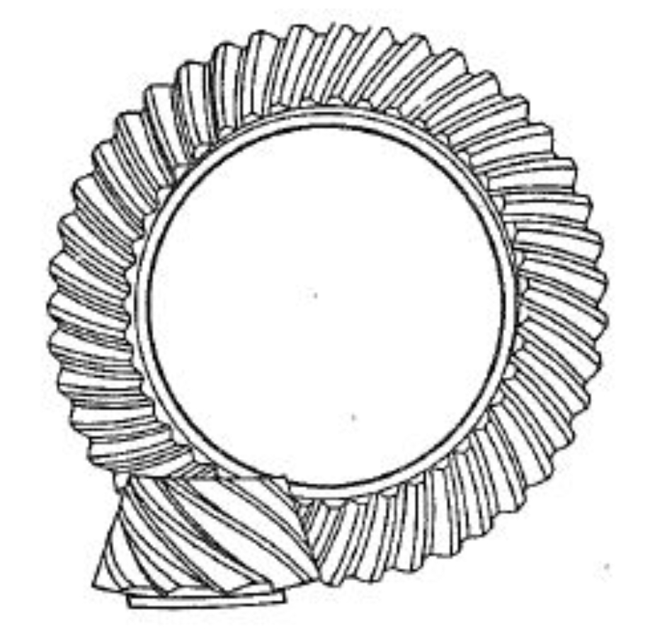
Hypoid gears are critical components in automotive final drive systems, balancing high load capacity with NVH performance. Proper backlash design ensures lubricant film formation, accommodates thermal expansion, and minimizes noise generation. This article systematically explores backlash determination through theoretical modeling, manufacturing tolerances, empirical measurements, and thermal deformation analysis.
Theoretical Framework for Hypoid Gear Backlash
The minimum required backlash for hypoid gears can be derived from the elastic deformation and thermal expansion criteria:
$$ J_{min} = \Delta L_{thermal} + \Delta L_{load} + h_{oil} $$
Where:
– $\Delta L_{thermal}$ = Thermal expansion component
– $\Delta L_{load}$ = Deformation under maximum torque
– $h_{oil}$ = Minimum oil film thickness (typically 0.5-1μm)
For automotive applications, the Gleason C-AGE software recommends initial backlash ranges based on pitch diameter:
| Pitch Diameter (mm) | Minimum Backlash (mm) | Maximum Backlash (mm) |
|---|---|---|
| 25.4 – 31.7 | 0.13 | 0.18 |
| 31.8 – 38.1 | 0.12 | 0.16 |
| 38.2 – 44.4 | 0.11 | 0.14 |
| 44.5 – 50.8 | 0.10 | 0.13 |
Manufacturing Tolerance Analysis
The cumulative effect of manufacturing errors on hypoid gear backlash is calculated as:
$$ \Delta J = \sqrt{F_{p1}^2 + F_{p2}^2 + F_{\beta1}^2 + F_{\beta2}^2} $$
Where $F_p$ represents single pitch tolerance and $F_\beta$ is helix angle tolerance. For Grade 7 hypoid gears (GB11365-89):
| Component | Tolerance (μm) |
|---|---|
| Pinion Pitch Error | 45 |
| Gear Pitch Error | 63 |
| Helix Angle Error | ±15 |
This results in a total backlash variation of ±0.109 mm for theoretically perfect assembly conditions.
Thermal Deformation Compensation
The thermal expansion component for hypoid gears operating at 70-150°C is calculated as:
$$ \Delta L_{thermal} = \alpha \cdot L \cdot \Delta T $$
Where:
– $\alpha$ = Thermal expansion coefficient (11.7×10⁻⁶/°C for steel)
– $L$ = Characteristic length (pitch diameter)
– $\Delta T$ = Temperature rise
For a 150mm pitch diameter hypoid gear:
$$ \Delta L_{thermal} = 11.7 \times 10^{-6} \times 150 \times 80 = 0.1404\ \text{mm} $$
Empirical Backlash Measurement Data
Field measurements from 50 final drive assemblies show characteristic backlash distribution:
| Measurement Phase | Minimum (mm) | Maximum (mm) | Mean (mm) |
|---|---|---|---|
| Pre-test | 0.11 | 0.18 | 0.145 |
| Post-test | 0.13 | 0.21 | 0.170 |
Backlash Optimization Strategy
The comprehensive backlash specification considering all factors becomes:
$$ J_{opt} = J_{theory} + \Delta J_{manufacturing} + \Delta J_{thermal} $$
$$ 0.13 + 0.109 + 0.107 = 0.346\ \text{mm}_{\text{max}} $$
Practical design limits for hypoid gears in automotive applications:
$$ 0.11\ \text{mm} \leq J_{operational} \leq 0.20\ \text{mm} $$
NVH Performance Considerations
Transmission Error (TE) as function of backlash:
$$ TE = K_1 \cdot J^{0.5} + K_2 \cdot J^{-1} $$
Where $K_1$ and $K_2$ are system stiffness coefficients. Optimal NVH performance occurs when $J$ maintains:
$$ 0.15\ \text{mm} \leq J \leq 0.18\ \text{mm} $$
This systematic approach to hypoid gear backlash design ensures reliable operation while meeting stringent automotive NVH requirements. The integration of theoretical modeling, manufacturing capability analysis, and empirical validation provides robust methodology for final drive development.