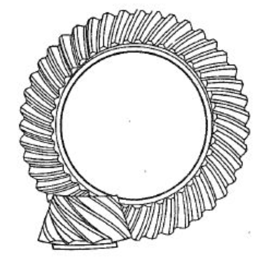
Hypoid gears are widely used in automotive and aerospace industries due to their high load capacity and smooth transmission. However, their complex manufacturing process requires precise control of machine tool adjustment parameters (MTPs) to ensure optimal meshing performance. This paper investigates the influence of MTPs on contact patterns, transmission errors (TE), and tooth surface profiles using mathematical modeling, tooth contact analysis (TCA), and mismatch topology analysis.
1. Mathematical Model of Hypoid Gear Tooth Surface
The tooth surface generation for hypoid gears involves coordinate transformations and kinematic relationships between the cutting tool and workpiece. For the pinion, the cutter surface in coordinate system \( S_p \) is expressed as:
$$
\mathbf{r}_p = \begin{bmatrix}
(r_{g1} + u_1 \sin \alpha_1) \cos \beta_1 \\
(r_{g1} + u_1 \sin \alpha_1) \sin \beta_1 \\
-u_1 \cos \alpha_1
\end{bmatrix}, \quad
\mathbf{n}_p = \begin{bmatrix}
\cos \alpha_1 \cos \beta_1 \\
\cos \alpha_1 \sin \beta_1 \\
\sin \alpha_1
\end{bmatrix}
$$
Transforming these into the pinion coordinate system \( S_1 \), the pinion tooth surface equation becomes:
$$
\mathbf{r}_1(u_1, \beta_1, \phi) = \mathbf{M}_{1p} \mathbf{r}_p, \quad
\mathbf{n}_1 = \mathbf{L}_{1p} \mathbf{n}_p
$$
where \( \mathbf{M}_{1p} \) and \( \mathbf{L}_{1p} \) are transformation matrices. The gear tooth surface is generated using formate cutting, with parameters listed in Table 1.
| Parameter | Pinion | Gear |
|---|---|---|
| Number of teeth | 7 | 43 |
| Module (mm) | 4.2 | 4.2 |
| Pressure angle (°) | 22.5 | 22.5 |
| Offset (mm) | 25.4 | – |
| Spiral angle (°) | 45 | 33.45 |

2. Tooth Contact Analysis (TCA) Model
The TCA model solves the kinematic compatibility conditions between pinion and gear surfaces:
$$
\begin{cases}
\mathbf{r}_{h1}(u_1, \theta_1, \phi, \phi_1, \mathbf{X}’) = \mathbf{r}_{h2}(u_2, \theta_2, \phi_2, E) \\
\mathbf{n}_{h1}(\theta_1, \phi, \phi_1, \mathbf{X}’) = \mathbf{n}_{h2}(\theta_2, \phi_2, E) \\
f(u_1, \theta_1, \phi) = \mathbf{n}_1 \cdot \mathbf{v}_1^{(12)} = 0
\end{cases}
$$
where \( \mathbf{X}’ \) represents MTPs with deviations \( \Delta \mathbf{X} \). Solutions to these equations determine contact paths and TE, calculated as \( \Delta \phi_2 = \phi_2 – (N_1/N_2)\phi_1 \).
3. Influence of MTPs on Meshing Performance
Key MTPs affecting hypoid gear performance include:
3.1 Displacement-Type MTPs
| Parameter | Contact Path Shift | TE Variation |
|---|---|---|
| Vertical wheel position (+0.1 mm) | Toe → Heel (concave) | +0.42% |
| Bed position (-0.1 mm) | Heel → Toe (convex) | -3.28% |
| Radial cutter position (+0.1 mm) | Root → Top | +23.6% |
3.2 Angular-Type MTPs
| Parameter | Contact Path Shift | TE Variation |
|---|---|---|
| Cutter blade angle (+0.1°) | Top → Root | +41.6% |
| Cutter tilt angle (-0.1°) | Heel → Toe | -27.2% |
| Machine root angle (+0.1°) | Root & Heel shift | +12% |
Radial cutter position and blade angle deviations exceeding 0.1 mm/° cause edge contacts, significantly increasing TE fluctuations.
4. Tooth Surface Mismatch Analysis
The mismatch \( m_{ij}^k \) between nominal and deviated surfaces is calculated as:
$$
m_{ij}^k = (\mathbf{r}_{ij}^k – \mathbf{r}_{ij}^1) \cdot \mathbf{n}_{ij}^1
$$
where \( \mathbf{r}_{ij}^1 \) and \( \mathbf{n}_{ij}^1 \) are the reference surface position and normal vectors. Mismatch patterns for critical MTPs include:
- Cutter blade angle deviation: Asymmetric pressure angle changes (up to 15 μm mismatch at the toe).
- Radial position error: Helix angle modifications causing 22 μm cumulative deviation.
- Machine root angle error: Combined spiral angle and pressure angle shifts (18 μm maximum mismatch).
5. Conclusions
- Displacement-type MTPs primarily affect contact path position along the face width, while angular-type parameters influence both profile and lengthwise contact patterns.
- Critical sensitivity rankings:
- Contact path: Radial cutter position > Vertical wheel position > Cutter blade angle
- TE magnitude: Cutter blade angle > Radial position > Machine root angle
- Mismatch analysis validates TCA results, showing maximum deviations at the gear toe and root regions.
Future work will incorporate thermo-mechanical effects and advanced error compensation strategies for hypoid gear manufacturing.
