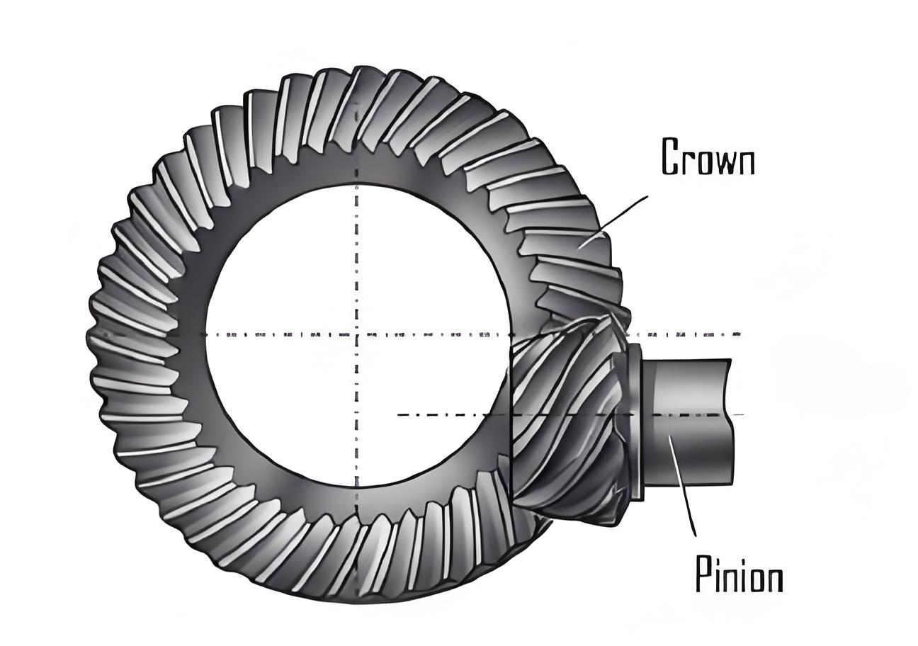
This study presents a comprehensive mathematical model for hypoid gear machining based on the Spiroflex (full generating) method, adapted for modern 6-axis CNC gear cutting machines. The methodology bridges traditional cradle-type machine settings with Cartesian-type CNC systems while maintaining the fundamental principles of hypoid gear generation.
1. Face Hobbing Tool Geometry
The cutting tool geometry for hypoid gears consists of blade groups with straight and rounded edges. The blade profile in coordinate system \( S_l \) is expressed as:
$$ \mathbf{r}_l(u) = \begin{bmatrix} x_l & 0 & z_l & 1 \end{bmatrix}^T $$
The straight-edge segment is defined by:
$$ \begin{cases}
x_l^{(l)}(\alpha_F; u) = \pm u \sin \alpha_F \\
z_l^{(l)}(\alpha_F; u) = u \cos \alpha_F
\end{cases} $$
For the rounded edge segment:
$$ \begin{cases}
x_l^{(f)}(\alpha_F; \rho_o; h_r; u) = \pm (x_{cf} – \rho_o \cos u) \\
z_l^{(f)}(\alpha_F; \rho_o; h_r; u) = z_{cf} + \rho_o \sin u
\end{cases} $$
where \( x_{cf} = h_r \tan \alpha_F + \rho_o \tan(0.4\pi – 0.5\alpha_F) \) and \( z_{cf} = h_r – \rho_o \).

2. Coordinate Transformations
The transformation from tool coordinate system \( S_t \) to imaginary generating gear system \( S_d \) is:
$$ \mathbf{r}_d(u, \beta, \phi_{c1}) = \mathbf{M}_{dt} \mathbf{r}_t(u) $$
Key transformation matrices include:
| Parameter | Symbol | Description |
|---|---|---|
| Tool Tilt Angle | \( \phi_i \) | 3-5° typical |
| Cradle Start Angle | \( \theta_c \) | ±60° range |
| Machine Root Angle | \( \gamma_m \) | 15-75° |
3. 6-Axis CNC Machine Configuration
The coordinate transformation for modern CNC hypoid gear cutting machines is expressed as:
$$ \mathbf{M}_{lt} = \mathbf{M}_{ll’} \mathbf{M}_{l’d} \mathbf{M}_{dc} \mathbf{M}_{cb} \mathbf{M}_{ba} \mathbf{M}_{at’} \mathbf{M}_{t’t} $$
Critical machine settings include:
| Parameter | Pinion | Gear |
|---|---|---|
| Blade Groups | 13 | 13 |
| Reference Height \( h_r \) | 3.99 mm | 4.05 mm |
| Pressure Angle \( \alpha_F \) | 20.9° | 16.3° |
4. Meshing Equation Derivation
The hypoid gear tooth surface is determined by solving the meshing equation:
$$ \mathbf{n}_1(u, \beta, \phi_c) \cdot \mathbf{v}_1^{(lt)}(u, \beta, \phi_c) = 0 $$
where the normal vector \( \mathbf{n}_1 \) and relative velocity \( \mathbf{v}_1^{(lt)} \) are derived from partial derivatives of the position vector.
5. Machining Simulation
Verification using VERICUT software demonstrated:
| Error Type | Pinion | Gear |
|---|---|---|
| Tooth Thickness Error | +3.8 μm | -39.6 μm |
| Surface Position Error | < 50 μm | |
The mathematical model achieved positional accuracy better than 30 μm across the hypoid gear tooth surfaces, validating its effectiveness for 6-axis CNC machining applications.
6. Industrial Implementation
Key advantages of this hypoid gear manufacturing approach include:
$$ \Delta E_{tooth} = \sqrt{(\Delta x)^2 + (\Delta y)^2 + (\Delta z)^2} \leq 50 \, \mu m $$
- Adaptability to modern CNC systems
- Accurate tooth flank modification capability
- Reduced setup time through digital twin simulation
This methodology provides a robust framework for high-precision hypoid gear production, particularly suitable for automotive differential applications requiring strict error control below 50 μm.
