
Hypoid gears are widely used in automotive rear axles due to their high load capacity, smooth transmission, and compact structure. This study focuses on epicycloid hypoid gears manufactured via face-hobbing with dual cutter heads. A mathematical model is established based on the generating principle, and the influence of assembly misalignments on meshing performance is investigated through tooth contact analysis (TCA).
Mathematical Modeling of Hypoid Gear Generation
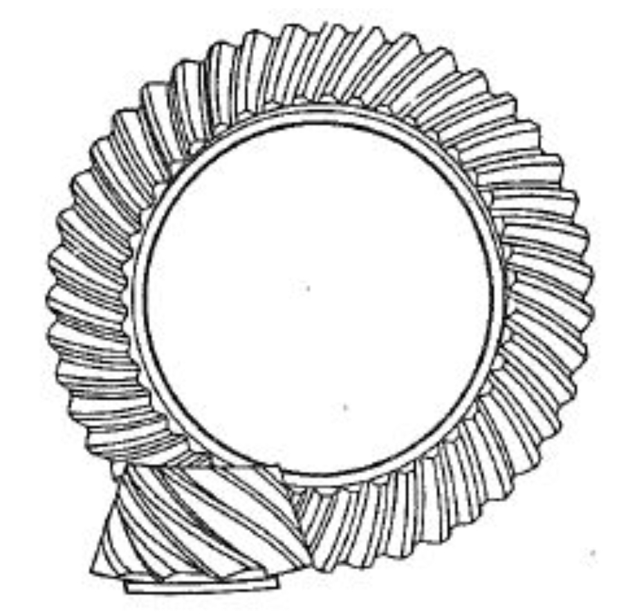
Face-Hobbing Process
Epicycloid hypoid gears are generated using a two-part cutter head (inner and outer blades) to produce convex and concave tooth surfaces. The cutter head rotates while the imaginary generating gear (crown wheel) rolls without sliding, forming extended epicycloidal tooth traces. The coordinate systems for the dual cutter heads are defined as follows:
$$
\begin{aligned}
\mathbf{r}_t(u) &= \mathbf{M}_{tp}\mathbf{M}_{pn}\mathbf{M}_{nm}\mathbf{r}_m(u), \\
\mathbf{r}_m(u) &= \begin{bmatrix} u\sin\alpha_{0k} \\ 0 \\ u\cos\alpha_{0k} \end{bmatrix}, \\
\mathbf{M}_{nm} &= \begin{bmatrix} \cos\delta_{0k} & -\sin\delta_{0k} & 0 \\ \sin\delta_{0k} & \cos\delta_{0k} & 0 \\ 0 & 0 & 1 \end{bmatrix}, \\
\mathbf{M}_{pn} &= \begin{bmatrix} 1 & 0 & r_{0k} \\ 0 & 1 & 0 \\ 0 & 0 & 1 \end{bmatrix}, \\
\mathbf{M}_{tp} &= \begin{bmatrix} \cos\beta_{ik} & -\sin\beta_{ik} & 0 \\ \sin\beta_{ik} & \cos\beta_{ik} & 0 \\ 0 & 0 & 1 \end{bmatrix},
\end{aligned}
$$
where \( \alpha_{0k} \), \( \delta_{0k} \), and \( r_{0k} \) represent the blade pressure angle, offset angle, and radius, respectively.
Tooth Surface Equation
The tooth surface of the hypoid gear is derived from the kinematic relationship between the cutter head and workpiece. The generating gear coordinate system \( S_d \) is expressed as:
$$
\begin{aligned}
\mathbf{r}_d(u, \beta, \phi_{c1}) &= \mathbf{M}_{dc}(\phi_{c1})\mathbf{M}_{cb}\mathbf{M}_{bt}(\beta)\mathbf{r}_t(u), \\
\mathbf{M}_{bt}(\beta) &= \begin{bmatrix} \cos\beta & -\sin\beta & 0 & E_{xz}\cos\phi_e \\ \sin\beta & \cos\beta & 0 & E_{xz}\sin\phi_e \\ 0 & 0 & 1 & 0 \end{bmatrix}, \\
\mathbf{M}_{cb} &= \begin{bmatrix} -\sin j & -\cos j & 0 & S_R \\ \cos j & -\sin j & 0 & 0 \\ 0 & 0 & 1 & 0 \end{bmatrix}, \\
\mathbf{M}_{dc} &= \begin{bmatrix} \cos(\theta_c – \phi_{c1}) & \sin(\theta_c – \phi_{c1}) & 0 \\ -\sin(\theta_c – \phi_{c1}) & \cos(\theta_c – \phi_{c1}) & 0 \\ 0 & 0 & 1 \end{bmatrix},
\end{aligned}
$$
where \( E_{xz} \), \( S_R \), and \( \phi_e \) denote the cutter eccentricity, radial distance, and positioning angle, respectively.
Tooth Contact Analysis with Assembly Errors
The TCA model accounts for three types of assembly misalignments: shaft angle error (\( \Delta\Sigma \)), axial displacement (\( \Delta H \)), and offset deviation (\( \Delta V \)). The meshing equations in the global coordinate system \( S_s \) are:
$$
\begin{aligned}
\mathbf{r}_s^{(1)}(u^{(1)}, \beta^{(1)}, \phi_1) &= \mathbf{r}_s^{(2)}(u^{(2)}, \beta^{(2)}, \phi_2), \\
\mathbf{n}_s^{(1)}(u^{(1)}, \beta^{(1)}, \phi_1) &= \mathbf{n}_s^{(2)}(u^{(2)}, \beta^{(2)}, \phi_2),
\end{aligned}
$$
where \( \mathbf{r}_s^{(i)} \) and \( \mathbf{n}_s^{(i)} \) represent the position and normal vectors of the pinion (i=1) and gear (i=2). The transmission error is calculated as:
$$
e(\phi_1) = \phi_2 – \phi_{20} – \frac{z_1}{z_2}(\phi_1 – \phi_{10}).
$$
Case Study: Hypoid Gear Design Parameters
A hypoid gear pair with the following parameters is analyzed:
| Parameter | Pinion | Gear |
|---|---|---|
| Module (mm) | 6.065 | 6.065 |
| Teeth Count | 12 | 49 |
| Offset (mm) | 40 | |
| Spiral Angle (°) | 42.922 (LH) | 30 (RH) |
| Parameter | Pinion | Gear |
|---|---|---|
| Cutter Radius (mm) | 135 (I), 135.39 (A) | 135 (I), 135.46 (A) |
| Pressure Angle (°) | 21 (I), -19 (A) | 19 (I), -21 (A) |
| Blade Offset Angle (°) | -6.4 (I), -6.429 (A) | 6.4 (I), 6.4265 (A) |
Impact of Assembly Misalignments
The TCA results under different assembly errors are summarized below:
- Shaft Angle Error (\( \Delta\Sigma = -0.05^\circ \)): Contact pattern shifts toward the toe-end with asymmetric transmission error.
- Axial Displacement (\( \Delta H = -0.1 \) mm): Contact zone moves toward the heel-end, increasing edge loading risk.
- Offset Deviation (\( \Delta V = 0.1 \) mm): Causes bias toward the toe on the concave side and heel on the convex side.
The sensitivity ranking of misalignments is: \( \Delta\Sigma > \Delta H > \Delta V \). Hypoid gears exhibit better misalignment absorption compared to straight bevel gears due to their curved tooth geometry.
Conclusions
This study establishes a comprehensive TCA methodology for hypoid gears considering assembly errors. Key findings include:
- The dual cutter head model accurately predicts epicycloidal tooth surfaces.
- Shaft angle errors have the most significant impact on contact patterns.
- Optimal adjustment of outer blade radius (\( r_{0A} \)) improves contact ellipse localization.
- Face-hobbing produces favorable parabolic transmission error curves for noise reduction.
The proposed approach enables robust hypoid gear design with enhanced tolerance to practical assembly variations in automotive applications.