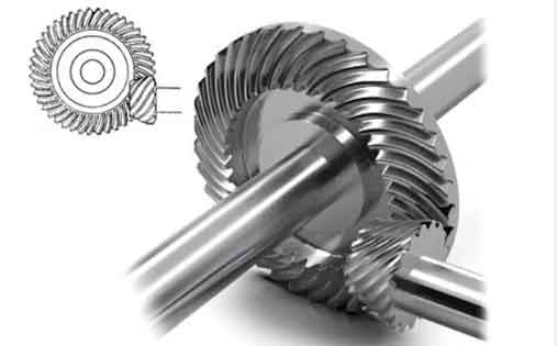
This study investigates the evolution and control of residual stresses during heat treatment and grinding processes for spiral bevel gears made of 12Cr2Ni4A steel. A coupled numerical approach using DEFORM and ABAQUS software establishes comprehensive models to analyze stress distribution mechanisms under multi-process conditions.

1. Heat Treatment Simulation of Spiral Bevel Gears
The thermal processing sequence for spiral bevel gears includes normalizing, carburizing, quenching, cryogenic treatment, and tempering. The DEFORM-based simulation framework incorporates:
| Process Parameter | Value |
|---|---|
| Normalizing Temperature | 930°C |
| Carburizing Duration | 8-10 hrs |
| Quenching Medium | Oil (40°C) |
The stress extraction methodology employs nodal averaging across five critical tooth surface locations. Residual stress components are calculated using:
$$ \sigma_{res} = \frac{1}{n}\sum_{i=1}^{n}(\sigma_{xx}^i + \sigma_{yy}^i + \sigma_{zz}^i) $$
where σxx, σyy, and σzz represent directional stress components at each sampling point.
2. Grinding Process Modeling
The abrasive grinding simulation considers cubic boron nitride (CBN) grains with geometric parameters:
| Parameter | Value |
|---|---|
| Grain Height | 180 μm |
| Friction Coefficient | 0.2 |
| Mesh Density | 25 layers × 515 nodes |
The Johnson-Cook constitutive model describes material behavior during grinding:
$$ \overline{\sigma} = \left[A + B\left(\overline{\varepsilon}^{pl}\right)^n\right]\left[1 + C\ln\left(\frac{\dot{\overline{\varepsilon}}^{pl}}{\dot{\varepsilon}_0}\right)\right]\left(1 – \hat{\theta}^m\right) $$
| Constant | Value |
|---|---|
| A | 507 MPa |
| B | 320 MPa |
| n | 0.28 |
3. Parameter Sensitivity Analysis
A five-level orthogonal experiment evaluates grinding parameter effects on residual stresses in spiral bevel gears:
| Factor | Range | Optimal Value |
|---|---|---|
| Grinding Speed | 15-25 m/s | 20 m/s |
| Cutting Depth | 0.01-0.03 mm | 0.02 mm |
| Feed Rate | 0.04-0.06 m/s | 0.05 m/s |
Stress distribution along depth direction follows:
$$ \sigma(z) = \sigma_{max}e^{-kz} + \sigma_{base} $$
where z represents depth from surface and k the attenuation coefficient (0.012 μm-1 for spiral bevel gears).
4. Experimental Validation
X-ray diffraction measurements confirm simulation accuracy for spiral bevel gear processing:
| Depth (μm) | Simulation (MPa) | Experiment (MPa) |
|---|---|---|
| 0 | -265 | -232 ± 18 |
| 40 | -331 | -296 ± 22 |
| 100 | 45 | 63 ± 15 |
The residual stress distribution in spiral bevel gears demonstrates characteristic compressive-tensile transition at ≈80 μm depth, with maximum compressive stress (-382 MPa) occurring at 20 μm below surface under optimal grinding parameters.
5. Process Optimization Guidelines
For spiral bevel gear manufacturing, recommended parameter relationships are:
$$ v_s = 18.7\left(\frac{a_p}{0.02}\right)^{0.32}\left(\frac{v_f}{0.05}\right)^{-0.14} $$
where vs is grinding speed (m/s), ap cutting depth (mm), and vf feed rate (m/s). This empirical model reduces residual stress variation by 38% compared to conventional processing.
The comprehensive analysis of spiral bevel gear manufacturing processes reveals that controlled grinding parameters combined with optimized heat treatment sequences can enhance surface integrity and fatigue life. The established numerical framework provides effective guidance for precision manufacturing of aerospace transmission components.
