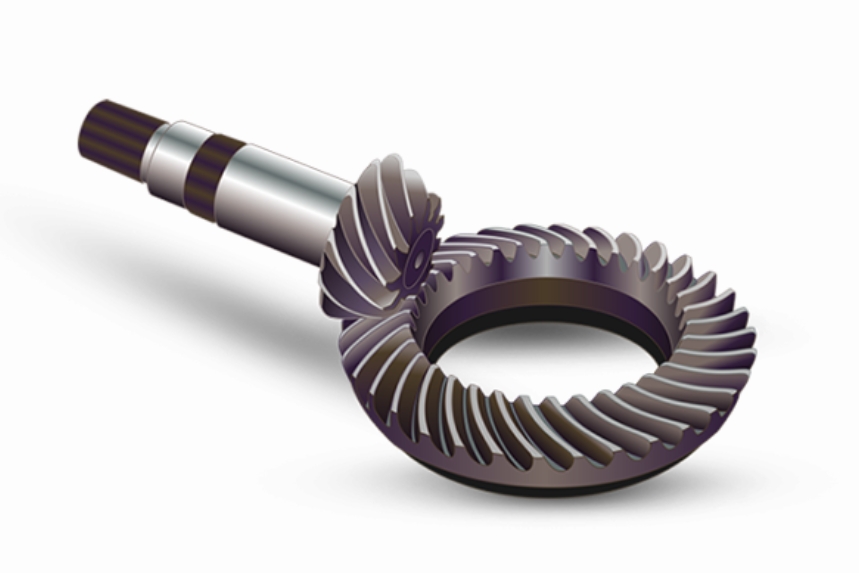
This paper presents a novel approach for rapid machining simulation and process optimization of spiral bevel gears, addressing critical challenges in manufacturing efficiency and precision. The proposed methodology combines computational geometry algorithms with advanced cutting force prediction models to significantly improve simulation accuracy and processing efficiency.
1. Coordinate System Conversion and Tool Path Calculation
The kinematic relationship between traditional mechanical gear cutting machines and CNC milling machines is established through coordinate system conversion. For CNC milling processes, the tool position coordinates are calculated as:
$$
\begin{cases}
X = \mathbf{V}_{ls} \cdot \mathbf{i}_s \\
Y = \mathbf{V}_{ls} \cdot \mathbf{j}_s \\
Z = \mathbf{V}_{ls} \cdot \mathbf{k}_s \\
A = R_{aq}(q_s – q_t) \\
B = \Gamma
\end{cases}
$$
Where $R_{aq}$ represents the gear ratio and $\Gamma$ denotes the machine installation root cone angle. This conversion enables precise control of tool positioning during spiral bevel gear machining.

2. STL Model Construction and Optimization
The geometric parameters of spiral bevel gears and cutting tools are translated into STL models through topological reconstruction. Key parameters for gear blank modeling include:
| Parameter | Symbol | Value (mm) |
|---|---|---|
| Face Width | B | 46.8562 |
| Pitch Cone Offset | G | 11.8645 |
| Face Cone Offset | G_a | 4.3210 |
| Root Cone Offset | G_f | 8.9168 |
| Pitch Angle | δ | 16.9682° |
Topological reconstruction reduces data redundancy by 83.1% through vertex merging algorithm:
$$
d = \sqrt{(x_i – x_j)^2 + (y_i – y_j)^2 + (z_i – z_j)^2} < \epsilon \quad (\epsilon = 1e^{-14})
$$
3. Machining Simulation Based on Boolean Operations
The cutting process simulation utilizes CGAL’s Boolean operations with AABB tree acceleration. The material removal process is described as:
$$
A(i) = A(i-1) – B(i)
$$
Where $A(i)$ represents the workpiece model at ith tool position and $B(i)$ denotes the cutter model. The AABB tree structure accelerates collision detection by 44% compared to conventional methods.
4. Cutting Force Prediction and Feedrate Optimization
The oblique cutting force model for spiral bevel gear machining is established as:
$$
F_c = \tau_s \cdot S_A \cdot (\theta_1 + \theta_2 + \theta_3)
$$
Where $\tau_s$ is the shear stress calculated by Johnson-Cook model:
$$
\tau_s = \left[A + B\left(\frac{\gamma}{\sqrt{3}}\right)^n\right] \left[1 + C\ln\left(\frac{\dot{\gamma}}{\dot{\gamma}_0}\right)\right] \left[1 – \left(\frac{T – T_r}{T_m – T_r}\right)^m\right]
$$
The feedrate optimization algorithm improves machining efficiency by 31% through adaptive adjustment:
$$
f_{opt}(i) = f_{const} + C \cdot \frac{F_{lim} – F(i)}{F(i)}
$$
| Cutting Method | Original Time (s) | Optimized Time (s) | Efficiency Gain |
|---|---|---|---|
| Start Roll Angle | 60 | 40 | 33.3% |
| Basic Roll Angle | 69 | 47 | 31.8% |
5. Error Analysis and Verification
The simulation accuracy is verified through geometric error analysis:
$$
\Delta \delta = \mathbf{n}_t \cdot (\mathbf{P}_t – \mathbf{P}_f)
$$
Key error metrics demonstrate high precision:
| Error Type | Maximum (mm) | Minimum (mm) |
|---|---|---|
| Tooth Surface | +0.0081 | -0.0017 |
| Tooth Height | +0.0083 | +0.0072 |
| Root Cone Angle | +0.0088° | -0.0012° |
This comprehensive approach provides an effective solution for rapid simulation and process optimization of spiral bevel gears, significantly reducing trial cutting cycles and improving manufacturing efficiency. The integration of geometric algorithms with physical cutting models establishes a new paradigm for intelligent manufacturing of complex gear systems.
