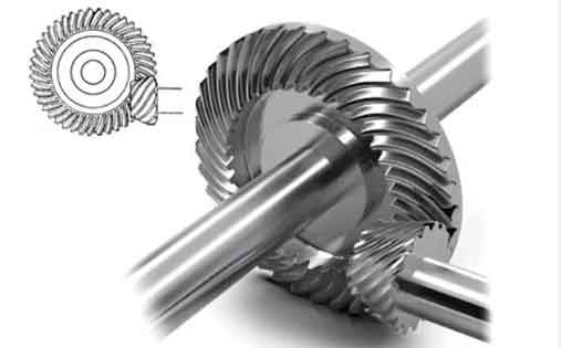
This paper investigates the duplex helical method for machining spiral bevel and hypoid gears, focusing on its cutting kinematics, mathematical modeling, and tooth contact behavior. A novel approach for machine setting calculation and ease-off topography design is proposed, validated through numerical simulations and physical experiments.

1. Mathematical Model of Duplex Helical Method
The fundamental coordinate systems for spiral bevel gear generation are established as follows:
$$
\begin{cases}
\mathbf{e}_m = [0\ 1\ 0]^T \\
\mathbf{g} = [\cos\gamma_m\ 0\ -\sin\gamma_m]^T \\
\mathbf{p} = [\cos(\Sigma-\gamma_m)\ 0\ -\sin(\Sigma-\gamma_m)]^T
\end{cases}
$$
Where $\gamma_m$ represents machine root angle and $\Sigma$ denotes shaft angle. The cutter normal vector $\mathbf{n}_0$ and tangent vector $\mathbf{t}_0$ at reference point M are derived as:
$$
\mathbf{n}_0 = \begin{bmatrix}
-\cos\alpha_{21}\sin\beta_{02} \\
-\cos\alpha_{21}\cos\beta_{02} \\
\sin\alpha_{21}
\end{bmatrix}
$$
$$
\mathbf{t}_0 = \begin{bmatrix}
-\sin\alpha_{21}\sin\beta_{02} \\
-\sin\alpha_{21}\cos\beta_{02} \\
-\cos\alpha_{21}
\end{bmatrix}
$$
2. Machine Settings Calculation
Key machine settings for spiral bevel gear manufacturing include:
| Parameter | Pinion | Gear |
|---|---|---|
| Radial setting (mm) | 132.962 | 135.671 |
| Cutter tilt angle (°) | 14.198 | – |
| Machine root angle (°) | -8.488 | 69.972 |
| Ratio of roll | 5.886 | – |
The spiral motion coefficient $H_l$ is determined by:
$$
H_l = \frac{r_{c1} + r_{c2}}{2\tan\beta_m}
$$
Where $r_{c1}$, $r_{c2}$ are cutter point radii and $\beta_m$ denotes mean spiral angle.
3. Ease-off Topography Design
The proposed ease-off calculation method uses generating surfaces instead of conjugate surfaces:
$$
\Delta\mathbf{r}_{ij}^{EO} = \mathbf{r}_{ij}^G – \mathbf{r}_{ij}^{Pg}
$$
Where $\mathbf{r}_{ij}^G$ represents gear tooth surface and $\mathbf{r}_{ij}^{Pg}$ denotes pinion generating surface.
4. Numerical Verification
A hypoid gear pair (7×43) was analyzed with following parameters:
| Parameter | Value |
|---|---|
| Module (mm) | 6.861 |
| Offset (mm) | 25.4 |
| Pressure angle (°) | 22.5 |
| Spiral angle (°) | 45/33.75 |
The transmission error (TE) results show:
$$
\Delta\phi_{\text{max}} =
\begin{cases}
12” & \text{(Drive side)} \\
13” & \text{(Coast side)}
\end{cases}
$$
5. Loaded Contact Analysis
Finite element analysis under 1000 N·m torque reveals:
$$
\sigma_{\text{max}} =
\begin{cases}
505.5\ \text{MPa} & \text{(Gear)} \\
300.6\ \text{MPa} & \text{(Pinion)}
\end{cases}
$$
6. Experimental Validation
Physical rolling tests exhibit consistent contact patterns with numerical simulations, verifying the proposed methodology’s accuracy in spiral bevel gear design and manufacturing.
Conclusion
The duplex helical method demonstrates superior efficiency in spiral bevel gear production, particularly for hypoid gears with complex geometry. The developed mathematical model and ease-off calculation approach provide effective tools for optimizing tooth contact characteristics and manufacturing precision.
